About the Series
This series of articles is designed to present the set of core UML diagrams in a way that emphasizes the important relationships between the different diagrams and the logical progression from one diagram to another.
In this installment we progress from the UML Use Case Diagram to the UML Sequence Diagram.
Introduction
A UML Sequence Diagram is used most commonly to show the realization of a use case in terms of interactions between business entities or software objects. This diagram therefore helps with the transition from non-object oriented activity diagrams and use case diagrams to the object-oriented paradigm of modern software development.
The sequence diagram is arranged in the form of a strict top-to-bottom timeline of interactions – or message exchanges – between business entities or software objects.
Diagram Elements
The number and type of diagram elements will vary according to the UML diagramming tool, the version of UML, and the context in which the diagram is to be used. Our subsequent worked example will utilize the following diagram elements that should be available in most if not all UML tools.
 |
An Object Lifeline is a vertical line headed by the name and / or classifier type of a business entity or software object. Messages may be sent to or from an object lifeline in strict sequential order from the top of the lifeline to the bottom. |
|
 |
A Message from one Object Lifeline to another is indicated by a horizontal line with an arrowhead showing the direction of the message. The message label text describes the behavior that the message sender is requesting from the receiver. |
|
 |
A Message to Self loops back from an Object Lifeline to itself, to show that the business entity or object performs some internal behavior. |
|
 |
A Message (return) is a dashed message line showing that control is returned to the originator of a message. |
|
 |
A Constraint is a UML construct showing (for example) that one behavior {OR} another may be invoked. |
While this table of diagram elements is informative, the only way to truly appreciate the role of the UML Sequence Diagram is via a concrete worked example.
Worked Example
For each of the use cases shown on the Use Case Diagram, the business analyst will have written a Use Case Specification that details the steps required to realize the use case functionality. In this worked example I offer a cut-down use case specification that will drive the creation of the corresponding Sequence Diagram.
The Use Case Specification
Brief Description
This use case describes how a bank customer withdraws money from his or her bank account.
Actors
(Bank) Customer
Basic Flow of Events
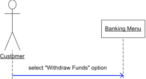
- The Customer selects the “Withdraw Funds” option from the Banking Menu.
- The Banking Menu causes the Withdraw Funds Form to be displayed.
- The Customer enters the withdrawal amount into the Withdraw Funds Form.
- The amount is withdrawn from the Customer Account.
- The Withdraw Funds Form displays a confirmation of the withdrawal.
- Control is returned to the Banking Menu.
Alternative Flow
4.1 If insufficient funds are available, the Insufficient Funds extension use case is triggered.
Pre-conditions
The customer must be logged in to his or her account.
Post-conditions
The amount withdrawn has been deducted from the customer’s account balance.
The Sequence Diagram
Now we present the UML Sequence Diagram that realizes the behavior of the Use Case Specification as a series of business entity or object interactions.
Notice how the series of messages corresponds almost exactly with the steps of the use-case flow. For example: where the use case specification states that “the amount is withdrawn from the Customer Account” we see a corresponding message in the sequence diagram representing the action to withdraw amount from the Customer Account. It is not necessary to label the message exchanges with sequential numbers (though some analysts do) because the sequence is implied in the top-to-bottom ordering of the interactions.
Notice how a UML {OR} constraint has been used to indicate the point at which the alternative extension use case may be triggered. This {OR} constraint may not be available in all UML tools and all UML versions, so you may have to use another diagram element – such as a simple note – to indicate this behavior. Notice how an object lifeline has been used to represent the Insufficient Funds extension use case, which (when triggered) requires no further explanation at this level because there should be an entirely separate sequence diagram showing the behavior of the extension use case.
Tips and Tricks
Each use case should be realized by one or more sequence diagrams; ideally a separate diagram for each possible use-case flow or ‘scenario’. If you find that you have a named use case with no corresponding sequence diagram(s), your UML software design may not be incomplete.
The series of steps that realize a use case may be represented using an alternative form of UML ‘interaction diagram’ – the Collaboration Diagram – as shown below. Since sequence diagrams and collaboration diagrams show essentially the same information, albeit in different forms, in many UML tools it is possible to generate a collaboration diagram automatically from a sequence diagram… and vice versa.
Since there is no implicit top-to-bottom time ordering in a collaboration diagram, the messages must be labeled explicitly with a number sequence. This alternative form of interaction diagram is particularly useful in visualizing the relationships between business entities or software objects, but collaboration diagrams seem to have fallen out of favor in recent years.
The sequence diagram given earlier represents an analysis-level sequence diagram as it may have been drawn by a business analyst. This diagram may be refined further by the software designer or developer to show more detail on how the proposed behavior will be implemented in software as a sequence of operation calls from one object to another. Like this:
Notice how the object lifelines are now represented as object class types (e.g. “: BankingMenu”) or as named object instances with their class types (e.g. “customerAccount : BankAccount”). Notice how, in many cases, the informal messages have been replaced with prospective object responsibilities or operations such as the operation “debit(amount:Long)” that is invoked on the BankAccount object.
The bottom line here is that the software analyst, designer, or developer is formalizing the transition from business concepts to potentially programmable ‘objects’; which leads us neatly onto…
Next Stop: The UML Class Diagram
Having identified potential objects and operations (or ‘methods’) during the creation of our sequence diagrams, we are now in a position to model the logical relationships between those objects using the UML Class Diagram.
Author: Tony Loton, Author
Tony Loton has authored and co-authored the books “Professional UML with Visual Studio .NET”, “Professional Visual Studio 2005 Team System”, and “UML Software Design with Visual Studio 2010”