About the Series
This series of articles is designed to present the set of core UML diagrams in a way that emphasizes the important relationships between the different diagrams and the logical progression from one diagram to another.
In this installment we progress from the UML Sequence Diagram to the UML Class Diagram.
Introduction
The UML Class Diagram, sometimes known as the Static Structure Diagram, shows the dependencies and persistent associations between object classes.
Diagram Elements
The number and type of diagram elements will vary according to the UML diagramming tool, the version of UML, and the context in which the diagram is to be used. Our subsequent worked example will utilize the following diagram elements that should be available in most if not all UML tools.
|
|
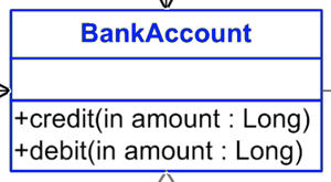
An object Class is represented by a rectangle containing the class name (in this case “BankAccount”) along with compartments for the attributes and operations.
|
|
|

|
The Operations compartment lists the object’s responsibilities which may be defined as methods in code. Each operation comprises the visibility or access modifier (+ for public, - for private, and # for protected), the operation name, and (in parentheses) the parameters that make up the operation signature.
|
|
|

|
The Attributes compartment lists the object attributes which often take the form of private variables. Each attribute has a visibility or access modifier, a name, and (after the “:”) a type.
|
|
|
|
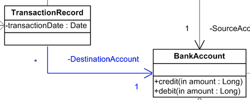
An Association is a solid line showing that instances of two object classes are related in some persistent sense. The association may be directional (i.e. navigable in only one direction) as indicated by an arrowhead. The multiplicity of 1, n, or * (meaning many) shows how object instances of one class are associated with a given instance of the other class. Optionally, each end of the association may be given a role name – in this case “DestinationAccount” – that helps distinguish multiple associations between the same two classes.
|
|
|

|
Aggregation is a stronger form of association, a whole-part or container-contained relationship, indicated by a hollow diamond. The yet stronger form of association known as Composition is indicated by a solid diamond.
|
|
|

|
A Dependency is a dashed line showing that one class depends on the presence or behavior of another class, but there are no persistent connections between the object instances.
|
|
|
|
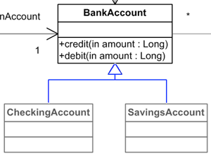
A Generalization is an inheritance relationship indicated by a solid line with hollow triangle attaching the super-class to its sub-classes.
|
While this table of diagram elements is informative, the only way to truly appreciate the role of the UML Class Diagram is via concrete worked examples.
Worked Examples
In the following worked examples we first construct a ‘participating classes’ diagram from the information given in a use case specification, and then we begin to expand the diagram into a more comprehensive representation of the entire system.
Participating Classes Diagram
Each use case that we define will typically have an associated UML Sequence Diagram that shows how business entities and / or software objects will interact in order to provide the use case functionality. Each use case specification will also typically have a UML Class Diagram known as a ‘participating classes diagram’ that shows the static relationships between those classes.
The participating classes diagram will be devised from the use case sequence diagram and / or the use case specification. The following diagram has been devised from the information given in the UML Use Case Specification for the Transfer Funds use case. With reference to the original use case specification, try to interpret the following diagram and then read through the explanation that follows.

The original use case specification alludes to the fact that Transfer Funds use case makes use of imported functionality and extension functionality provided by the Select Account use case and the Insufficient Funds use case. By devising a set of Controller classes that will orchestrate the behaviors of the use cases we not only adhere to a proven object oriented ‘design pattern’ but also achieve a way of modeling the inter-relationships between these use cases in the form of UML dependencies between the controllers. Notice how each controller class has a run() responsibility modeled as an operation.
According to steps 4 and 5 of the use case specification, a SourceAccount undergoes a debit of the specified amount and a DestinationAccount receives a credit. These are not separate classes, i.e. one of which you can debit and the other of which you can credit. All bank accounts can be credited and debited, and so the correct way to model the distinction in this case is to use role names – SourceAccount and DestinationAccount – on the associations that connect two BankAccount instances with a TransactionRecord class that records the result of the overall transaction.
The TransactionRecord class records the transactionDate using a private attribute, and each TransactionRecord is associated with exactly one BankAccount in the role of SourceAccount and exactly one BankAccount in the role of DestinationAccount. Any given BankAccount may be associated with many (*) TransactionRecords for funds transfers made on different dates.
Extending the Class Diagrams
Having devised a ‘participating classes’ diagram for a specific use case, we might go on to think about how those classes relate to other classes in the proposed software system as a whole. Here is a first attempt:
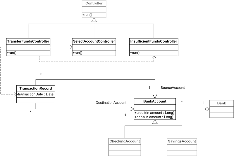
This enhanced diagram introduces the generalization notation indicating that a generic Controller class may be conceived as a generalization of the TransferFundsController, SelectAccountController and InsufficientFundsController classes. From a more business-oriented perspective we might determine that the BankAccount class is in fact a generalization of the more specialized CheckingAccount and SavingsAccount subclasses.
The diagram also utilizes the aggregation notation to show that a single (multiplicity 1) Bank class representing the entire bank contains or owns many (multiplicity *) BankAccounts.
Tips and Tricks
One thing that often triggers debate among UML practitioners is the distinction between aggregation (the hollow diamond on an association line) and composition (the filled diamond). From a programmer’s point of view the distinction is often between associated classes being held ‘by reference’ within the containing class or ‘by value’. This distinction doesn’t really help the analyst, and in any case most programming languages these days reference all contained objects ‘by reference’. For the analyst it is more a question of sharing and immutability, for example:
Aggregation: On the tax authority’s computer system my personal record may be aggregated with an employer’s record because (in a sense) I ‘belong to them’ until I leave; but I might also be aggregated with a different employer’s record if I’m holding down two jobs simultaneously. Contrary to what I might hope, neither employer depends on my existence.
Composition: A Country is composed of, among other things, a Capital City. No two countries can have the same capital city, and it could be argued that a country without a capital city is simply not a valid country.
By their very nature, participating classes diagrams will be limited in the number of classes they include – because only so many classes can participate in each use case. When it comes to representing the complete set of relationships between all of the classes that comprise the software solution, you will find that a single class diagram becomes unwieldy.
A solution to this problem is to structure the classes into packages, rather like I suggested for use cases. Each package may have its own class diagram showing the interrelationships between the closely-related classes it contains, and an overall class diagram (the package diagram) can be used to represent the overall structure of the software solution like this:
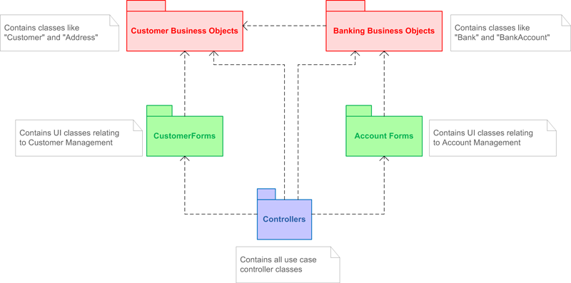
Implicit in this approach is the possibility of the same class being included on more than one class diagram, but do not despair – a class will be defined just once in the UML Model regardless of the number of diagrams on which it appears.
Next Stops: The UML State Diagram and UML Component Diagram
The definition of object classes on one or more class diagrams leads logically onto two more UML diagrams:
TO DO: Test your UML knowledge with a quick UML & Use Case Quiz.
Author: Tony Loton, Author
Tony Loton has authored and co-authored the books “Professional UML with Visual Studio .NET”, “Professional Visual Studio 2005 Team System”, and “UML Software Design with Visual Studio 2010”