About the Series
This series of articles is designed to present the set of core UML diagrams in a way that emphasizes the important relationships between the different diagrams and the logical progression from one diagram to another.
In this installment we progress from the UML Activity Diagram to the UML Use Case Diagram.
Introduction
Use case diagrams are used to show the decomposition of a business problem or software solution into a set of discrete functions (the use cases) which can be enacted by or on behalf of users (the actors). In a nutshell, this diagram shows who (the actors) can do what (the use cases) when interacting with the software solution.
Use case diagrams were contributed to the Unified Modeling Language (UML) by Ivar Jacobson, who had devised them as part of his Objectory software development method for documenting user requirements.
Diagram Elements
The number and type of diagram elements will vary according to the UML diagramming tool, the version of UML, and the context in which the diagram is to be used. Our subsequent worked example will utilize the following diagram elements that should be available in most if not all UML tools.
|

|
An Actor is a person or another software entity (such as a system timer) that initiates the functionality provided by a Use Case.
|
|
|
|
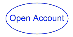
A Use Case is a unit of functionality provided by a software solution to one or more Actors.
|
|
|
|
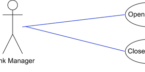
The Communicates or Association line indicates that a particular Actor makes use of the functionality provided by a particular Use Case.
|
|
|
|
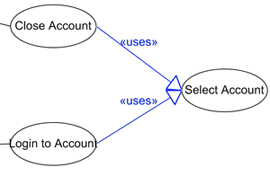
A <<uses>> (or more recently <<import>>) relationship shows how one Use Case makes use of ‘reusable’ functionality provided by another Use Case.
|
|
|

|
The <<extends>> (or more recently <<extend>>) relationship shows how the functionality of a Use Case may be extended or enhanced by some optional functionality provided by another Use Case.
|
While this table of diagram elements is informative, the only way to truly appreciate the role of the UML Use Case Diagram is via a concrete worked example.
Worked Example
Take a look at the following worked example of a use case diagram that decomposes the ‘banking’ business into a set of atomic functions that may be performed by various actors. Try to interpret the diagram yourself and then read my description that follows.
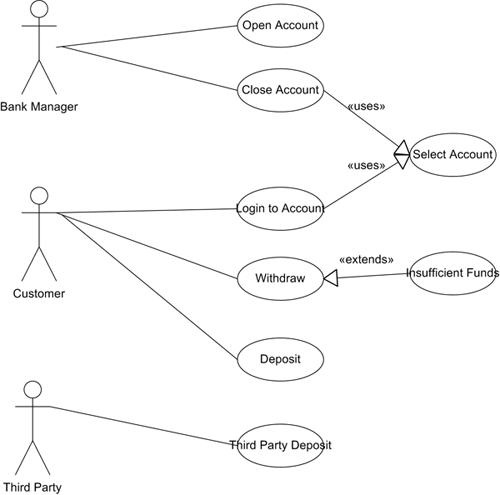
In this diagram:
-
The Bank Manager actor can perform the two functions represented by the Open Account and Close Account use cases.
-
In order to Close Account (but not open it) a specific account must first be selected, and this potentially reusable account selection functionality has been factored out into a separate Select Account use case which the Close Account use case <<uses>>. Note that the newer UML terminology would show that the Close Account use case imports the functionality of the Select Account use case.
-
The Customer actor can Login to Account, and in the process must specify or select a particular account to login to. Hence the Login to Account use-case also <<uses>> the functionality provided by the Select Account use case.
-
The Customer actor can Deposit to his account, and Withdraw amounts from his account, but in the latter case only if sufficient funds are available. In the case of Insufficient Funds being available, the use case of this name <<extends>> the base functionality by denying the request or generating an over-drawing fee that will be charged to the customer’s account.
-
The Third Party actor can make a Third Party Deposit to a customer’s bank account, but for obvious reasons he is not allowed to make a withdrawal from an account he doesn’t own.
Tips and Tricks
Each use case shown on the Use Case Diagram will be backed by a detailed use case specification that is written by the business analyst and which describes how the use case will be ‘realized’ as an interplay between business entities. Since this article presents use case diagrams rather than use case specifications, I refer you to the next article in this sequence which will formalize a use case specification as a series of object interactions.
While a Use Case Diagram decomposes a system’s functionality and shows which functions are performed by which system users, this diagram does not imply any order in which those functions must be performed. For example, this diagram does not tell us that the Open Account use case must be enacted by the Bank Manager actor before the Deposit and Withdraw use cases may be enacted by the Customer actor. This is where the earlier Activity Diagram (the previous article in this series) comes in useful as a way of arranging the use cases in the form of activities in the correct sequence. In this context it is most useful to achieve correspondence between use cases with activities and actors with swim lanes. By referring to the original activity diagram for the banking business process, can you spot a use case for the Customer actor that is missing from this worked example?*
When decomposing a business problem into a set of use cases, it is important for each use case to be named using a strong verb and to have a well-defined atomic function. For example: in the context of a word processing package, a ‘Check Spelling’ use case would be more appropriate than a less-well-definable ‘Produce Document’ use case.
The <<uses>> and <<extends>> relationships represent stereotypes of the generic communicates relationship. In UML, the stereotype mechanism allows a single diagram element to represent different concepts according to how the diagram element is labeled with a <<stereotype>>.
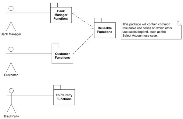
A single diagram need not – and, in fact, should not – show every actor and use case, with the general recommendation being that no diagram should span more than one printed page. Furthermore, it may be useful to arrange the use cases into packages of functionality such as (in our example) the ‘Bank Manager functions’, the ‘Customer functions’ and the ‘Third Party functions’, with perhaps an additional package representing the ‘reusable functions’. Not only does this diagram (below) help to collect groups of use cases into packages such that each set may be represented by its own diagram, but also it suggests a modular arrangement of system functions for incremental delivery.
Next Stop: The UML Sequence Diagram
So far on our UML journey we have seen how the Activity Diagram may be used to describe an overall business process, with swim lanes and activities that we can use as a mechanism for decomposing the business problem or software solution into an arrangement of actors and use cases in the Use Case Diagram. But how will those use cases be implemented or ‘realized’ as a series of interactions between business entities or software objects? We’ll find the answer to this question on our next stop: the UML Sequence Diagram.
* The answer to the question posed earlier is that the Logout of Account use case is missing.
TO DO: Test your UML knowledge with a quick UML & Use Case Quiz.
About the Author: Tony Loton has authored and co-authored the books “Professional UML with Visual Studio .NET”, “Professional Visual Studio 2005 Team System”, and “UML Software Design with Visual Studio 2010”