Every software team talks about project scope and team members often complain about unending scope creep. Unfortunately, the software industry lacks uniform definitions of these terms, and the requirements literature is short on clear guidance regarding how to even represent scope. I confront scope head-on in this series of three articles, adapted from my book More about Software Requirements (Microsoft Press, 2006). I’ll present some definitions, describe four techniques for defining project scope, and offer some tips for managing scope creep.
Vision and Scope
I regard the vision and scope document is a key software project deliverable. You can find a suggested template for this document at http://www.processimpact.com/goodies.shtml. Other terms for this type of guiding document are a project charter, market (or marketing) requirements document, and business case. You don’t necessarily need a standalone vision and scope document for a small project. Any project of any size, though, will benefit from such strategic guidance, even if it’s just a paragraph or two at the beginning of the software requirements specification.
Both the vision and the scope are components of the project’s business requirements. I think in terms of the product vision and the project scope. I define the product vision as: “A long-term strategic concept of the ultimate purpose and form of a new system.” The product vision could also describe the product’s positioning among its competition and in its market or operating environment. Chapter 5 of my book Software Requirements, 2nd Edition describes how to write a concise vision statement using a simple keyword template.
I’ll define project scope as: “The portion of the ultimate product vision that the current project or iteration will address. The scope draws the boundary between what’s in and what’s out for the project.” The second part of the project scope definition is most important. The scope identifies what the product is and is not, what it will and won’t do, what it will and won’t contain.
A well-defined scope sets expectations among the project stakeholders. It identifies the external interfaces between the system and the rest of the world. The scope definition helps the project manager assess the resources needed to implement the project and make realistic commitments. In essence, the scope statement defines the boundary of the project manager’s responsibilities.
Your scope definition also should include a list of specific limitations or exclusions—what’s out. Obviously, you can’t list everything that’s out of scope because that would include every detail in the universe except for the tiny sliver that is in scope for your project. Instead, the limitations should identify capabilities that a reader might expect to be included in the project but which are not included. I know of a project to build a Web site for a national sports team that included the following exclusions for the initial release:
- There will be no virtual or fantasy games via the Web.
- The demographic details for newsletters will not be collected.There will be no betting facilities available.
- There will be no ticketing facilities on the site.
- Message boards are out of scope for phase 1.
Some stakeholders involved with this project might have expected these capabilities to be included. Itemizing them as exclusions makes it clear that they won’t be. This is a form of expectation management, an important contributor to project success.
The rest of this article describes two techniques I’ve found useful for depicting project scope, the context diagram and the use case diagram. In part 2 of the series, I’ll describe two additional techniques, feature levels and system events.
Context Diagram
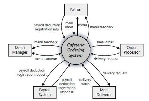
The venerable context diagram dates from the structured analysis revolution of the 1970s. Despite its antiquity, the context diagram remains a useful way to depict the environment in which a software system exists. Figure 1 illustrates a partial context diagram for a hypothetical corporate cafeteria ordering system. The context diagram shows the name of the system or product of interest in a circle. The circumference of the circle represents the system boundary. Rectangles outside the circle represent external entities, also called terminators. External entities could be user classes, actors, organizations, other software systems to which this one connects, or hardware devices that interface to the system.

Figure 1. A sample context diagram
The interfaces between the system and these external entities are shown with labeled arrows, called flows. If the “system” is strictly an electronic system involving software and perhaps hardware components, flows will represent data or control signals. However, if the “system” includes both a software application and manual operations, flows could also represent the movement of physical objects. Two-headed flows indicate update operations involving the data object on the flow.
The context diagram depicts the project scope at a high level of abstraction. This diagram deliberately reveals nothing about the system internals: no information about functionality, architecture, or look-and-feel. Nor does it explicitly identify which features or functionality are in scope and which are not. The functional behavior of the system is merely implied by the labeled flows that connect the system to the external entities. Even the flows are labeled at a high level of abstraction, just to keep the diagram’s complexity manageable. The business analyst can decompose these data flows into individual data elements in the project’s data dictionary or data model. Corresponding data inputs and outputs imply the types of operations the system will perform, but these aren’t shown explicitly in the context diagram.
Despite the limited view that the high level of abstraction imposes, the context diagram is a helpful representation of scope. It serves as a tool to help the project stakeholders communicate about what lies outside the system boundary. A BA in a requirements class I once taught showed me a context diagram for her current project. She had shown this diagram to the project manager. The manager had pointed out that one of the external entities shown on the context diagram, another information system, was now going to be part of the new system. With respect to Figure 1, this would be like moving the Payroll System inside the project circle. That is, the scope of the project just got larger than the BA expected. She had expected that external system to be someone else’s responsibility, but now it was her problem.
Use Case Diagram
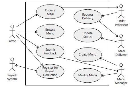
Use cases are a powerful technique for exploring user requirements. The Unified Modeling Language (UML) includes a use case diagram notation. Figure 2 shows a partial use case diagram for our cafeteria ordering system. The rectangular box represents the system boundary, analogous to the circle in a context diagram. The stick figures outside the box represent actors, entities that reside outside the system’s context but interact with the system in some way. The actors correspond approximately (exactly, in this example) to the external entities shown in rectangles on the context diagram.

Figure 2. A sample use case diagram.
Unlike the context diagram, the use case diagram does provide some visibility into the system. Each oval inside the system boundary box represents a use case. The use case diagram shows the interactions of the system with its users and some connections between internal system operations, albeit at a high level of abstraction.
The arrows on the use case diagram indicate which actors participate in each use case. In Figure 2, the arrow from the Patron to the oval labeled "Submit Feedback" means that the patron actor can initiate the Submit Feedback use case. The arrow from Submit Feedback to the Menu Manager actor indicates that the Menu Manager participates somehow in the execution of Submit Feedback. Arrows on the use case diagram do not indicate data flows as they do on the context diagram. Some analysts simply draw lines instead of arrows on the use case diagram to avoid any confusion with data flow. In addition to showing these connections to external actors, a use case diagram could depict logical relationships and dependencies between use cases.
The use case diagram provides a richer scope representation than the context diagram because it provides a high-level look at the system’s capabilities, not just at its external interfaces. There is a practical limitation, though. Any sizeable software system will have dozens of use cases, with many connections among them and between use cases and actors. Attempting to show all those objects inside a single system boundary box quickly becomes unwieldy. Therefore, the analyst needs to model groups of related use cases as packages or to create multiple use case diagrams.
Many analysts have found the context diagram and use case diagram to be helpful ways to represent and communicate a shared understanding of a project's scope. In Part 2 of this series, I’ll describe two other techniques for defining scope, feature levels and system events.
 Author: Karl Wiegers, Process Impact
Karl Wiegers is Principal Consultant at Process Impact, www.ProcessImpact.com. His interests include requirements, project management, peer reviews, and process improvement. This article is adapted from his book More About Software Requirements (Microsoft Press, 2006).