NOTE: This is article # 4 of a four articles series, where I describe why it is so valuable to create various views of your requirements. I’ll tell you about some of the analysis models and other techniques you can use to represent requirements information and give you some ideas about how to choose an appropriate model. You can find the first article here: The Six Blind Men and the Requirements
 There is no single correct way to document specific requirements information. Every BA needs a rich tool kit of techniques at her disposal so that she can choose the most effective requirements view in each situation. In this article, adapted from my book, More about Software Requirements (Microsoft Press, 2006), I offer some ideas about how to make that choice.
Often, it’s valuable to represent information at both high and low levels of abstraction. The high level offers a big-picture perspective, whereas the low level of abstraction presents the nitty-gritty details. Certain audiences only need the high-level view, whereas developers and testers do need to see all those specifics, as well. An effective requirements analysis technique is to create an alternative view of the requirements from the initial set of information and examine it for problems.
Here’s an actual example. I once reviewed a requirements specification for a client who was developing the firmware for a device for testing integrated circuit components. The spec contained a long table that listed the various states this device could be in and what behaviors lead to changes from one state to another. Table 1 shows a portion of this table. I needed to know if all possible states were described and that the allowed state changes were all correctly specified. But how could I judge that? Missing requirements are hard to spot precisely because they don’t exist.
Table 1. Partial Functionality Descriptions for a Real-Time System
|
Application State
|
Application Control
|
Description
|
|
Off
|
|
[functionality]
|
|
Power Up
|
|
[functionality]
|
|
Ready to Run
|
Go To Running
|
[functionality]
|
|
Running
|
-
Go To Shutdown
-
Go to Standby
|
The firmware enters the ‘Running’ state on request of the host from the states Ready to Run, Standby, Shutdown, and Error. Immediately after the state is entered, all data available in the firmware interface is sent to the host, and the firmware notifies the host that the ‘Running’ state is entered.
|
|
Standby
|
Go To Running
|
[functionality]
|
|
Shutdown
|
Go To Running
|
[functionality]
|
|
Error
|
Go To Running
|
[functionality]
|
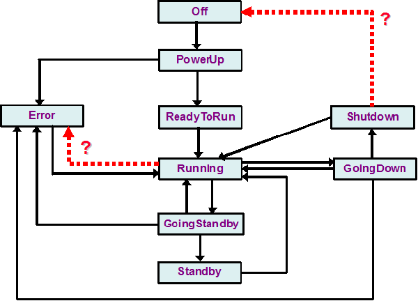
I decided to draw a state-transition diagram from the information in the original table, which appears in Figure 1. A state-transition diagram is an analysis model that provides a high-abstraction view of such a system. It shows the various states the system could be in at a given time (rectangles), the permitted transitions between states (arrows), and the conditions and actions that lead to each transition (could be written on the arrows if desired). The Unified Modeling Language has a similar notation called a state machine diagram.
Sure enough, I found some problems with this diagram, shown with the dotted red lines in Figure 1. First, the table contained no functionality to get to the Off state! That is, I expected to see an arrow in the diagram going from Shutdown to Off, but I found no requirement to make this happen. Also, the table didn’t mention the possibility of an error occurring while in the Running state. Thus, by creating this second view as an analysis tool, I identified a couple of missing requirements. Better now than later, I always say.
Figure 1. State-Transition Diagram for a Real-Time System

Table 2 suggests techniques that are appropriate for representing various types of information at both high and low levels of abstraction. Chapter 11 of my book Software Requirements, 2nd Edition (Microsoft Press, 2003) provides more details on many of these methods and contains references to additional sources to learn about these techniques. Use this table to help you select appropriate techniques for documenting your requirements information.
Table 2. Choosing the Most Appropriate Requirements Views
|
Information Depicted
|
Representation Techniques
|
|
System external interfaces
|
-
The context diagram and use case diagram identify the objects outside the system that connect to the system. The context diagram illustrates the system inputs and outputs at a high level of abstraction.
-
External interface details can be recorded in format descriptions for input and output files, or report layouts. Products that include both software and hardware components often write interface specifications with data attribute definitions, perhaps in the form of an application programming interface or specific input and output signals for a hardware device.
|
|
Business process flow
|
-
A top-level data flow diagram represents a business process at a high level of abstraction. Swimlane diagrams show the roles that participate in executing the various steps in a business process flow.
-
Refined data flow diagrams and swimlane diagrams can represent business process flows in considerable detail. Flowcharts and activity diagrams can be used at either high or low abstraction, although usually they are used to define the details of a process.
-
A natural language procedure description provides the greatest business process detail.
|
|
Data definitions and data object relationships
|
-
The entity-relationship diagram shows the logical relationships between data objects (entities). Class diagrams show the logical connections between object classes and the data associated with them.
-
The data dictionary contains detailed definitions of both data structures and their constituent data items.
|
|
System states
|
-
State-transition diagrams and state machine diagrams represent a high-abstraction view of the states a system can be in and the changes between states that can take place under certain circumstances.
-
Some BAs create an event-response table as a scoping tool (high abstraction), identifying external events that help define the product’s scope boundary.
-
You can specify individual functional requirements with an event-response table that details how the system behaves in response to combinations of external event and system state.
|
|
Behavior of an object that can take on multiple statuses
|
-
The state-transition diagram and state machine diagram show the possible statuses of the object and the changes from one status to another. These models are helpful when multiple use cases can change the status of the objects.
-
Functional requirements describe exactly what user and system behaviors lead to status changes.
|
|
Complex logic
|
-
A decision tree is a diagram that shows the possible outcomes from a set of related true/false decisions or conditions.
-
A decision table identifies the unique functional requirements associated with the various combinations of true and false outcomes for a series of decisions or conditions.
|
|
User interfaces
|
-
The dialog map provides a high-level view of a proposed or actual user interface, showing the various display elements (for example, screens and dialog boxes) and possible navigation pathways between them.
-
Storyboards and low-resolution prototypes flesh out the dialog map by showing what each screen will contain without depicting precise details.
-
Detailed screen layouts and high-resolution prototypes show exactly what the display elements will look like. Data field definitions and user interface control descriptions provide additional detail.
|
|
User task descriptions
|
-
User stories, scenarios, and use case specifications describe user tasks in various levels of specificity and detail.
-
Sequence diagrams illustrate the interplay between multiple actors and the system during execution of a use case. Flowcharts and activity diagrams visually depict the flow of the use case dialog and branches into alternative flows and exceptions.
-
Functional requirements provide detailed descriptions of how the system will behave under specific conditions. Test cases provide an alternative low-abstraction view, describing exactly what system behavior to expect under particular combinations of inputs, system state, and actions.
|
|
Nonfunctional requirements (quality attributes, constraints)
|
-
Quality attributes and constraints are usually written in the form of structured text, but that often results in a lack of precision and completeness. The definitive technique for precisely specifying nonfunctional requirements is Planguage, a flexible and powerful keyword notation developed by Tom Gilb.
|
About Author :

Karl Wiegers is Principal Consultant at Process Impact, www.ProcessImpact.com. His interests include requirements engineering, project management, peer reviews, and process improvement. His most recent book is a memoir of life lessons titled Pearls from Sand: How Small Encounters Lead to Powerful Lessons (www.PearlsFromSand.com).