About the Series
This series of articles is designed to present the set of core UML diagrams in a way that emphasizes the important relationships between the different diagrams and the logical progression from one diagram to another.
Introduction to the Activity Diagram
Unified Modeling Language (UML) Activity Diagrams are rather like traditional flowcharts that may be used to describe the steps required to enact high level business processes or low level algorithms. From the software analyst’s perspective these diagrams are most useful for representing business processes, so this will be our focus here. Whereas activity diagrams are often relegated to the final chapters of the UML text books, I prefer to present them up-front as the logical starting point for any UML analysis and design endeavor. The reason for this will become apparent when you see subsequently how the swim lanes and activities of the activity diagram correspond with the actors and use cases of the UML Use Case Diagram.
Diagram Elements
The number and type of diagram elements will vary according to the UML diagramming tool, the version of UML, and the context in which the diagram is to be used. Our subsequent worked example will utilize the following diagram elements that should be available in most if not all UML tools and which are particularly relevant to the software analyst rather than the software developer.
|

|
A Swim Lane is a vertical channel that arranges all of the activities performed by or on behalf of a particular actor; in this case the activities of the Bank Manager actor.
|
|
|

|
The Initial State or Initial Activity is a filled circle that marks the beginning of the process described by the diagram.
|
|
|

|
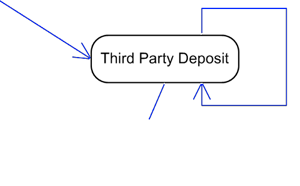
An Activity or State (the terminology can vary) is a lozenge shape that shows when a particular activity is being undertaken by, or on behalf of, the actor who is represented by the swim lane in which the activity / state is placed.
|
|
|
|
A Transition or Control Flow is a directional line that shows the flow of control between activities. A Self-Transition shows the flow of control from an activity back to itself such that the activity repeats.
|
|
|

|
A Decision is a diamond shape indicating that control may flow in one of a number of directions depending (for example) on a [guard condition] being satisfied.
|
|
|

|
A Transition (Fork) is a horizontal line that shows how a single flow of control may split into two or more parallel streams of activities. Such parallel behavior was difficult to show using traditional flow charts.
|
|
|

|
A Transition (Join) is a horizontal line indicating the point at which several parallel streams of activities must synchronize into a single stream.
|
|
|

|
An Object In State is a rectangle showing that a particular object or business entity exists in a particular state as result of an activity, and an Object Flow is a dashed line indicating which activity has affected the object-in-state.
|
|
|

|
The Final State or Final Activity is a filled circle with a concentric ring that marks the end of the process described by the diagram.
|
While this table of diagram elements is informative, the only way to truly appreciate the role of the UML Activity Diagram is via a concrete worked example.
Worked Example
Take a look at the following worked example of an activity diagram for a ‘banking’ business process that utilizes the elements just cataloged. Try to interpret the diagram yourself and then read my description that follows, keeping in mind that there is some degree of art as well as science in the usage and interpretation of the UML constructs.

Following on from the initial activity, the first real activity is the one in which the Bank Manager actor performs the activity to Open Account, thus resulting in the creation of a new Bank Account.
Once the account is opened, two parallel streams of activity may ensue:
-
A Third Party actor may make a Third Party Deposit to the account (but no withdrawals from it) any number of times while the account is open.
-
The account Customer may Login to (his) Account and choose between making a Deposit or Withdrawal, by choosing the relevant menu option to satisfy the [deposit] or [withdraw] guard condition. The account Customer can perform the Logout of Account activity by choosing the relevant menu option and satisfying the [logout] guard condition of the Decision point.
-
At the end of its life, the Bank Account may be closed by the Bank Manager who performs the Close Account activity, but only if the two parallel streams of activities have concluded such that the Customer is logged out of the account and the Third Party is no longer making deposits.
While this example – in common with most software engineering ‘text book’ examples – has been contrived in order to demonstrate a range of constructs, it is representative of the kind of business process that we can develop further through the range of UML diagrams.
Tips and Tricks
As stated in the introduction, activity diagrams may be used for a variety of purposes in a UML modeling project. Not only to model overarching business processes as described here, but also to model business rules or the internal algorithms that realize particular use cases or object methods. Care should be taken to model only non-trivial use cases and methods in this way, and to utilize the more object-oriented UML Sequence Diagrams to model lower level interactions.
Although the UML is an object-oriented software design notation, activity diagrams are not overtly ‘object oriented’ in their form and function, which makes them accessible to business analysts from traditional non-object oriented backgrounds and readable by end-users.
Some UML modeling tools do not support activity diagrams at all, in which case you may be able to adapt the UML State Diagram for the same purpose. State diagrams employ essentially the same diagram elements albeit with different names, so you can (for example) use a State shape to represent an Activity. Where a particular modeling tool obliges you to attach a State diagram to a software object or business entity, it is feasible to devise an entity to represent the entire business process – let’s call this entity or object the BankingBusinessProcess in our running example – and attach the State Diagram (now acting as an Activity Diagram) to it.
Next Stop: The UML Use Case Diagram
As suggested at the outset, the swim lanes and activities of the UML Activity Diagram may correspond with the actors and use cases of the Use Case Diagram, so our next port of call on the road to becoming proficient with UML should be the UML Use Case Diagram.
TO DO: Test your UML knowledge with a quick UML & Use Case Quiz.
About the Author : Tony Loton has authored and co-authored the books “Professional UML with Visual Studio .NET”, “Professional Visual Studio 2005 Team System”, and “UML Software Design with Visual Studio 2010”