This article discusses the difference between models and diagrams. Its content includes:
- What is the difference between a model and a diagram
- When to use a model and when to use a diagram
- The benefits of models versus diagrams
- Examples of diagraming notations and tools
- Examples of modeling languages and tools
- Where to find more information
- This article uses the term ‘notation’ when referring to diagrams and ‘language’ when referring to models.
- This article uses the term ‘element’ when referring to something that can be viewed on a diagram, and ‘component’ when referring to something that can be viewed in a model explorer.

Overview
A long time ago, when I was teaching the Rational Unified Process (and UML), the terms model and diagram were used interchangeably. This caused significant confusion amongst the teachers and of course, this affected our ability to educate students unambiguously. As a result of realizing the root cause of the problem, I set about producing definitions for these terms. The purpose was to make sure that the right term was used in the correct context.
Quote from Google: “A model is an abstraction that contains all the elements needed to describe the intention of the thing being modeled. This can include all aspects concerning the business, systems, relationships, and more. A diagram is a specific view into what you are trying to understand in a specific context.”
Let us assume that the ‘thing’ being modeled already exists. A model of this thing contains known information up to a specified level of abstraction. (I.e. the model does not capture everything known about the thing, but only information to the level of detail that we are interested in.) A diagram shows this model information from the point of view of specific stakeholder.
For example: Let the ‘thing’ be a house. A model may capture all information about the house that is greater than 1 metre in size. A plumber type stakeholder is only interested in water pipes and their connections. A view into the model for the plumber would be a diagram showing the house water pipes (to an accuracy of 1 metre in size).
Benefits Of Creating A Model
A model provides an abstract vision of the product, which is faster and cheaper to build than the actual product itself. Models provide benefit when the return on investment of maintaining the model is greater than the cost of creating the model. (The value of maintaining the model often decreases, as the product development increases.) A model is a 3D representation of the product that can be used by everyone:
- Users – Can be sold on the product before it is built
- Project Managers – Can track the progress of the product against the model
- Architects – Gain a visual representation of the foundations of the product
- Auditors - Can give preliminary approval prior to the product being built
- Testers – Can write test cases against the model, before the product is built
- Developers – Get a visual representation of the current and future product while building in the product details
When to use a Model
Use a model, when multiple stakeholder types need to be able to understand information about the state of the deliverable. The model is constantly updated, so that this information may be presented over the course of the project.
Prior to construction - when you need to be able to describe what is going to be built, without needing to know the accuracy of every detail.
During construction - when you need to be able to describe what has been built so far, without needing to know the accuracy of every detail.
After construction - when you need to be able to describe what was built, without needing to know the accuracy of every detail.
The model is constantly changing to reflect:
- What is expected to be built
- What is currently being built
- What was actually built
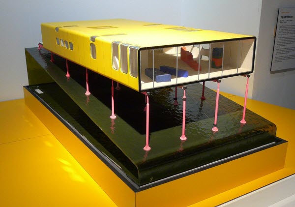
Figure 1: shows a 3-dimensional representation of the ‘thing’ under consideration.

Figure 1: Figure 1: Example Model
When to use a Diagram
Use a diagram to present information about the deliverable to a single stakeholder type. The information in the diagram shows a snapshot in time. When the diagram needs to be continuously updated, it may be more efficient to generate the diagram from a model.
If a model is a 3-dimensional abstraction of a thing, then a diagram may be considered to be a 2-dimensional view into the model of that thing.
A diagram provides an abstract picture of the thing, at a specific point in time, for a specific audience.
If a diagram is created from a model, then diagram is automatically regenerated when the model changes.
Figure 2: shows a 2-dimensional representation of the ‘thing’ under consideration.

Figure 2: Example Diagram
Diagramming Notations
A notation describes the rules for drawing a specific type of diagram. A business analyst may find the following diagram types useful:
- Activity diagrams – Use to capture a complex process flow
- Business Process Diagram – Use to describe the interactions between people in a business process
- Class diagram – Use to capture the structure of information as classes, their operations and relationships
- Communication diagram – Use to show messages that are passed between objects
- Data flow diagram – Use to represent a hierarchy of processes and the data flowing between those processes
- Flowchart – Use to visualize a software process flow
- Sequence diagram – Use to show communication between users, systems and objects
- State transition diagram – Use to describe the states of and object and the transitions between states
- Use case diagram – Use to capture functionality from a user’s point of view
Modeling Languages
A modeling language describes a set of component types, the rules for their use and relationships between them. A diagram contains a subset of modeling language rules. Diagrams used by a business analyst may be part of the following modeling languages:
- BPMN – Business Process Model and Notation is a language for describing business process flows from the perspective of the people involved in the process
- SA/SD - Structured analysis and design technique is a language used to model software systems using a top-down hierarchical structure
- Shlaer/Mellor – An object-oriented analysis and design language that can be used to simulate executing software
- SDL - Specification and Description Language is a structured analysis and design language that can be used to simulate executing software
- UML – Unified Modeling Language is an object-oriented language for describing the analysis and design of software systems
The Unified Modeling Language
UML is a merger of several object-oriented notations, combined with use cases. It is currently the most popular modeling language for software engineering. UML is not just a diagramming notation – it includes:
- Diagrams - The Superstructure that defines the notation and semantics for diagrams and their model elements
- Metadata - The Infrastructure that defines the core meta-model on which the Superstructure is based
- Functionality - The Object Constraint Language (OCL) for defining rules for model elements
- Interfaces - The UML Diagram Interchange that defines how UML diagram layouts are exchanged
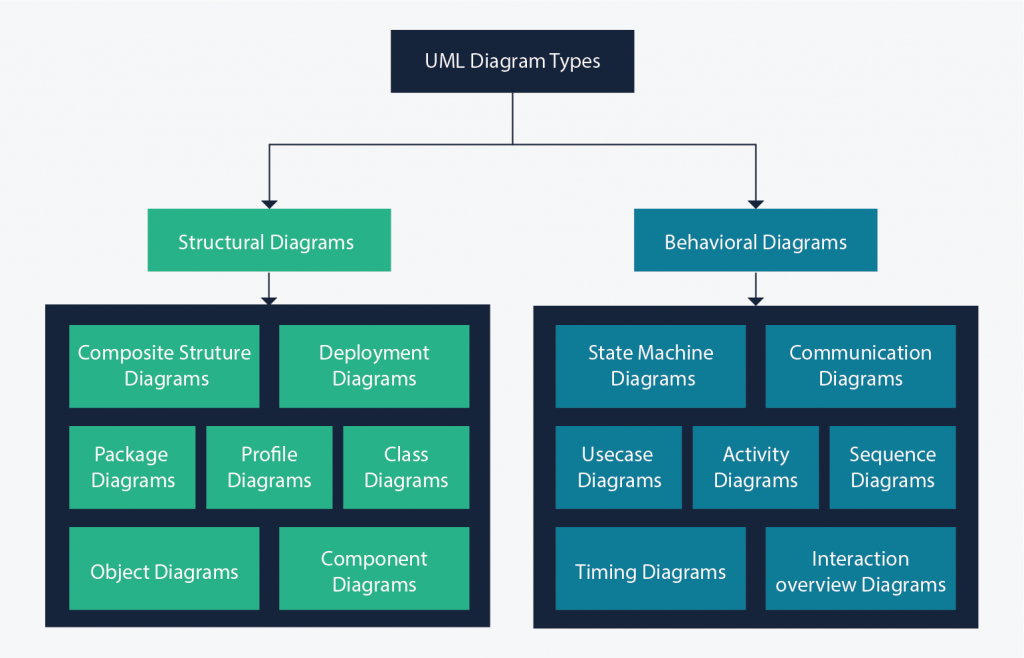
Figure 3: shows the diagram types that are included in UML. (Click on the diagram to open a link to Creately containing information about the diagram types.)

Figure 3: UML Diagram Types
- Note that a modeling language may include more rules than those provided by the set of its diagram types.
Diagramming Tools
Diagramming tools allow the business analyst to create a picture of the feature under discussion, without having to build a model structure or create components. Common diagramming tools that may be used by a business analyst include:
- Creatly – An online drawing tool that supports many notations, including UML and flowcharts
- Lucidchart – An online drawing tool for UML diagrams
- Paint – A freehand drawing tool that is useful for marking up existing images
- Visio – Microsoft drawing tool that allows diagrams to be created from templates containing predefined components for the diagram type
- \Note that diagramming tools do not fully support UML. UML includes additional rules to those contained within the notation of its diagram types.
- Note that Visio Professional version 2007 provided support for UML model navigation. This was removed from the 2010 version.
Modeling Tools
Modeling tools include diagramming tools and a model navigator. Components placed on a diagram include information about the component that can be viewed and edited through the model navigator. They will often include the ability to create reports and documentation. Example modeling tools include:
- ARIS – BPMN modeling tool
- Enterprise Architect – Supports UML, BPMN and several other modeling languages
- Erwin – Used for database modeling
- Rational Software Architect - Supports UML, BPMN and several other modeling languages
- Visual Paradigm - Supports UML, BPMN and several other modeling languages
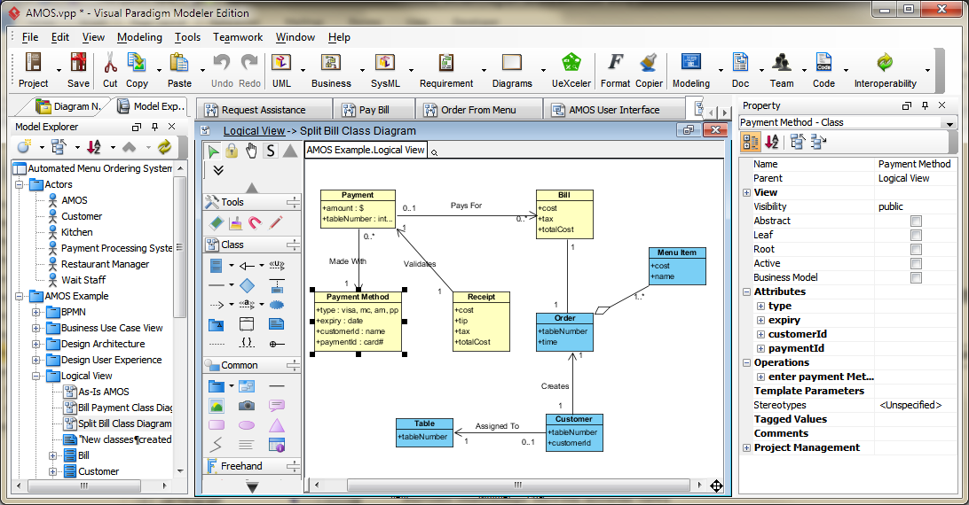
Figure 3: shows some features of a typical modeling tool. The various windows show:
- The model navigator – Lists model components organized into packages (folders)
- A diagramming tool – Includes a canvas and template for the components of the displayed diagram type
- Component properties – Displays the properties of the selected component (or diagram)

Figure 4: Example Modeling Tool
- This image is taken from Visual Paradigm; my preferred modeling tool.
Benefits of Modeling
Models are best used for long term capture of information about a deliverable, where many stakeholders will use that information. A model is especially useful during the complete software development lifecycle and beyond.
- Captures information that can be used by all stakeholders in a single repository
- Provides relationships between different views (using diagrams) into the model
- Diagrams can be automatically generated from the model, so long as the diagram notation is supported.
- May include configurable reporting that is customized for specific stakeholder requests
- Modeling tools provide assistance with simulation of the model
- Modeling tools provide (some sort of) validation against the diagram languages and the model notation and may ensure compliance during editing of a diagram
Benefits of Diagramming
Diagrams are best used for short-term capture of deliverable information, where a small audience needs the information in the diagram.
- Diagramming tools have a small learning curve, compared to modeling tools
- Diagrams require little setup, compare to modeling tools, (because no model architecture is required)
- When you do not want to be bound by any specific notation, but want to create a freehand image using your own symbols
- A diagram that is needed for a short period of time, can be produced quickly
- If information is needed by a single stakeholder, then a diagram may be sufficient
- Some diagram templates include guidelines for creating the diagram according to its notation
Summary
A diagram is a 2-dimensional representation of a story, which shows elements and their relationships on a single canvas. An element is shown on a single diagram. (To show the same element information on a 2 diagrams, the element is duplicated.) When the properties of a diagram element are changed, the change is reflected only on that diagram.
A model is a 3-dimensional representation of a collection of related stories, which captures diagram elements as model components. A component includes all element properties and relationships between different elements on all diagrams. A single model component can be shown as elements on several diagrams. A change to the properties of a diagram element or model component is reflected on every diagram where that component is displayed.
A model does not necessarily need to include any diagrams. Diagramming is the most common method for creating and maintaining model components, but the diagrams can be deleted without changing the model.
If a picture is worth a thousand words, then a diagram converts those words into a story. A model organizes those stories into a book.
Modeling References
UML 2 Specification
See Appendix B.6 UML Notations and Representations page 704
Analysis Through Pictures
By Leslie Munday ([email protected])
BPMN 2.0 Specification
See section 7.2 for a list of elements
Author: Leslie Munday, Sr. IT Professional
Leslie is a Senior level Information Technology (IT) professional with expertise in Business and Systems Analysis, Process Analysis, Requirements Analysis and Project Management.
Previously, I published a book titled “Analysis Through Pictures”. This book details the knowledge, skills, methods and best practices that I used as a systems analyst, up to 2011. It shows how the Rational Unified Process can be used effectively, to produce quality software systems. I have been actively involved with the International Institute of Business Analysis. I joined the IIBA after they asked me to give a presentation about traceability. Since then I have presented an analysis model of the Business Analysis Body Of Knowledge, and published several analysis presentations to various business analysis organizations. My website is intended to share my analysis knowledge skills and presentations with anyone who is interested in learning about the role of a business analyst.