Consider the situation where you are the business analyst who is planning project work according to the BABOK guidelines. The project manager wants to plan their time spent on business analysis activities. You produce a report of the BABOK that shows tasks that the project manager is expected to contribute to.
Figure 1: shows the BABOK tasks where a project manager is a contributing stakeholder.
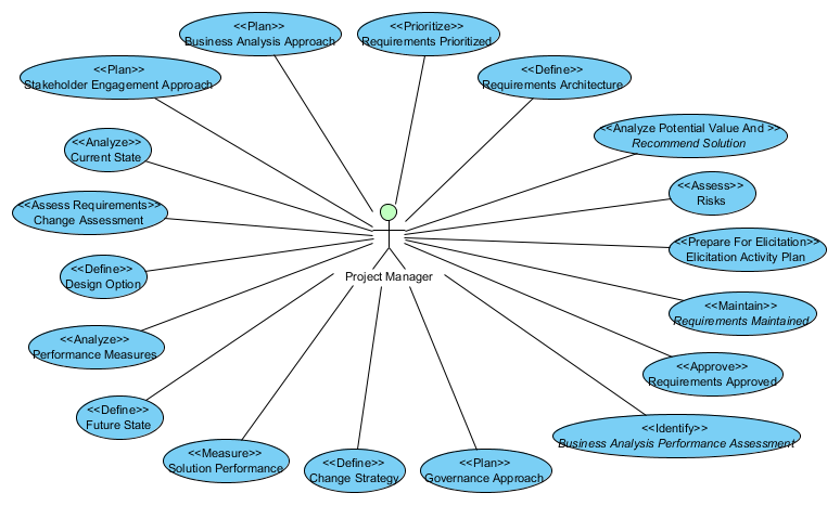
Figure 1:Project Manager Tasks
This diagram is generated from a model of the BABOK. Because this information is in a model, the project manager and business analyst can easily determine the extent to which each task will be executed and how much effort will be required.
The task names are the same as those in the BABOK, but formatted such that they are easy to reference within the modeling tool.
Overview
This article describes an analysis I performed of the Business Analysis Body Of Knowledge v3 (BABOK). The result of this analysis is a model contained in the Visual Paradigm modeling tool. This model captures 461 pages of the BABOK, from the Business Analysis Key Concepts chapter through to the end of the Techniques To Tasks Mapping chapter.
Visual Paradigm is my personal preference, but there are several modeling tools that are equally capable of hosting this model. Links to Visual Paradigm and to the model, are referenced at the end of this article.
The analysis breaks down the BABOK into object classes and their supporting components. A class details the object’s data and its functions. (See Specify and Model Requirements, BABOK section 7.1.)
The model architecture organizes these classes and supporting components, into packages. (See Define Requirements Architecture, BABOK section 7.4.)
Relationships between the model components capture traceability. (See Trace Requirements, BABOK section 5.1.)
Why Model?
What is the benefit of repeating BABOK information in a modeling tool (such as Visual Paradigm)?
This model came about when I was trying to understand the BABOK in order to address practice questions for CBAP certification. I realized that finding the information in the BABOK required a lot of searching. I wanted a more logical method for finding this information which uses clues in the question to find logical links to an appropriate answer. The information in the model is not simply repeated using a graphical representation, but it is consolidated into an unambiguous set of guidelines.
The model captures components of the BABOK and the relationships between them. Types of component are; inputs, outputs, tasks, techniques, guidelines and tools. Once the relationships between these components are identified, the modeling tool automatically generates diagrams showing logical connections (traceability) between components. This allows the information to be displayed from many different viewpoints. One viewpoint allows you to focus on a particular component (or set of components) and see the relationships between those components and other components in the model. For example, Figure 2: shows the Business Analysis Approach artifact and its relationships to other artifacts.
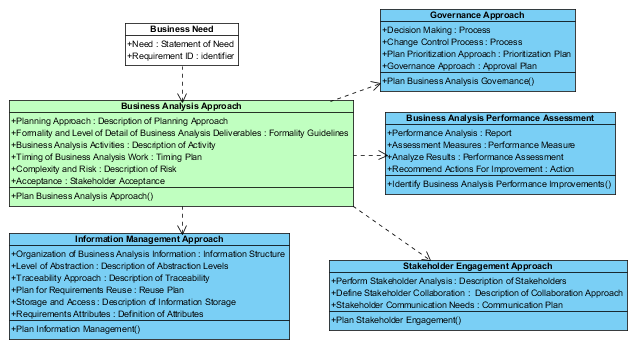
Figure 2:Business Analysis Approach Artifact Relationships
The component in question is colored green. Components colored white are external inputs to the business analysis. All other components are colored blue.
The BABOK is in a book format and as such it presents analysis information linearly. The book structure is enforced through chapters and subsections within chapters. A model allows you to define your own architecture and present the same information using any number of 2-dimensional diagrams. In addition, the model includes the same structure as the book, but it also contains a 3rd dimensional structure, through relationships between model components. This structure is hidden within the model, until it is exposed to the reader through diagrams.
In the rest of this article, I provide an overview of this model and some example diagrams showing how BABOK information can be extracted.
BABOK Version 3
The Business Analysis Body Of Knowledge v3 (BABOK) is the globally recognized standard for the practice of business analysis whose primary purpose is to define the profession of business analysis and provide a set of commonly accepted practices. The BABOK includes a process that is primarily focused on the tasks that are performed to generate outputs. Each task creates or updates one or more artifacts, which are then passed on to a subsequent task, or to a stakeholder. Each task is described in terms of:
- Purpose – A textual overview of the intent of the task
- Description – A detailed description of the task
- Inputs – A description of the information that the task uses
(This section also includes a diagram showing the inputs, guidelines and tools, outputs and tasks using those outputs.)
- Elements – These are task components that provide guidelines for executing the task
The model treats Elements as attributes of the artifact that is produced by the task. Each artifact attribute includes a reference back to the element in the BABOK.
- Guidelines and Tools – A brief description of how analysis guidelines and tools may be used by the task
Note that artifacts may also be guidelines.
- Techniques – A brief description of analysis techniques that may be used during the execution of the task
- Stakeholders – The people who provide input to the task or use the information produced by the task
- Outputs – The artifacts that are produced by the task
These tasks are grouped into 6 knowledge areas, where a knowledge area describes a specific business analysis area of expertise. In this manner, the BABOK presents its information in a top-down functional structure. Knowledge areas contain tasks, which contain techniques, outputs, stakeholders, etc., which contain a description.
Figure 3: contains a diagrammatic view of the BABOK structure.
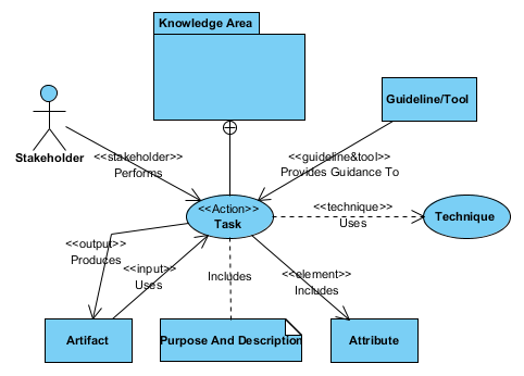
Figure 3:How The BABOK Is Organized
The main component is the Task. Tasks are organized into Knowledge Area packages. Tasks include elements (or attributes of the task) and a purpose and description. Tasks convert input artifacts into output artifacts using, techniques, guidelines and tools. Stakeholders assist with the task or take ownership of its outputs.
Not shown on the diagram – Techniques are collected into a Techniques package.
The Model
The model uses an object-oriented approach to capturing business analysis information. Object Oriented Analysis and Design (OOA/OOD) produces a model that focuses on the ‘real’ things (objects) in the BABOK. The result is a ‘flat’ structure that focuses on components and the relationships between them.
Artifacts
The primary component is the Artifact. Artifacts are described in the Inputs and Outputs sections of the BABOK. Artifacts are a class of objects that are defined by:
- attributes (Elements in the BABOK)
- operations (Tasks in the BABOK)
I added a unique identifier to each artifact. There is no equivalent element in the BABOK. For example, Requirement includes a Requirement ID attribute to uniquely identify each requirement.
Relationships between artifacts are captured using dependencies. (Dependencies are derived by connecting all of the inputs to the output of each task.)
Each artifact includes at least 1 operation (task), many attributes (element) and at least 1 relationship (dependency). An artifact may be generated by many tasks (operations), but a task produces (or updates) exactly 1 artifact.
Where the BABOK shows a task has more than 1 output, those output artifacts are combined, using an aggregation relationship, into a primary artifact containing secondary artifacts. Each artifact takes their own elements (or attributes), but the aggregation relationship indicates that that all artifacts take the same operations and the same relationships.
Figure 4: shows that the Future State includes a Potential Value and 1 or more Business objectives.
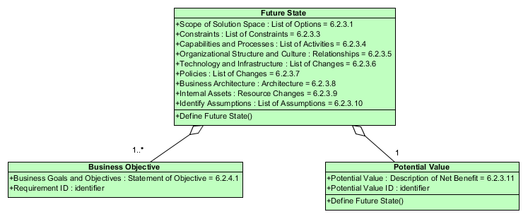
Figure 4:Example Aggregation
Note the attribute references their equivalent element paragraph number in the BABOK.
Although not shown on the diagram, it is implied that the Business Objective and Potential Value, both include a Define Future State operation.
Supporting Components
Stakeholders are represented by actors. Techniques and tasks are modeled with use cases. Guidelines/Tools are modeled with object (classes). Stakeholders, techniques, guidelines and tools are related to the appropriate task using Includes or Association relationships. The label on the relationship indicates if it is a technique or guideline/tool. The task is shown connected to its containing artifact with an association. Stakeholders are shown as actors connected to the artifact task.
Use cases are the most as appropriate representation for tasks and techniques, because they are functional. Classes are appropriate for guidelines/tools because they are static.
The model uses packages to represent knowledge areas, and the appropriate artifacts are assigned to their package. Figure 5: contains a diagrammatic view of the model structure.
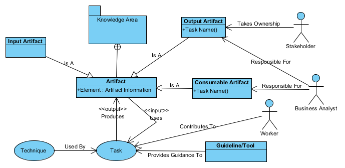
Figure 5:How Model Components Are Organized
When using a modeling tool, each component type can be located within its own folder; with folders for: Artifacts, Guidelines and Tools, Knowledge Areas, Stakeholders, Tasks and Techniques. The Artifacts folder is further divided into subfolders for: Consumables, Deliverables and Inputs.
- Consumable Artifact – Is produced by the business analyst and used as part of the business analysis process (I.e. they are both input to and outputs from tasks.)
- Deliverable Artifact – Is produced by the business analyst and used by stakeholders outside of the business analysis process (I.e. they are outputs from a task, but not inputs.)
- Input Artifact – Is used by the business analyst, but produced by stakeholders outside of the business analysis process (I.e. they are input to tasks, but not produced by a task.)
Creating The Model
The model structure was developed by first creating the packages that hold components (Artifacts, Tasks, Actors, Techniques, Guidelines and Tools and Knowledge Areas). The artifacts (inputs and outputs for each task) are added to the Artifacts package as classes. Tasks are added to the appropriate artifacts as operations. (The appropriate artifact is the primary artifact that is output by the task.) Elements are added to the appropriate artifact as attributes. (The appropriate artifact is derived from the element description.) When several artifacts are output by a task, only one contains the element.
It is not always clear what information is being produced from the element name. Therefore I clarify the attribute name by adding a ‘type‘ to the attribute that identifies the output from the element. Figure 4: shows several examples, such as Potential Value is of type ‘description of the net benefit’.
Next the Inputs/Outputs, Guidelines and Tools, Techniques and Stakeholders section for each task in the BABOK, are captured using 4 diagrams. Each diagram is attached to the primary artifact that is output by the task, as a child diagram.
These 4 diagram types capture all the relevant information in the BABOK.
The Usage Diagram
This is a class diagram that shows all the input and output artifacts connected to the artifact (for all tasks producing the Artifact as an output). Figure 6: shows the usage diagram for the Requirement artifact.
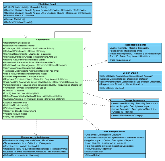
Figure 6:Requirement Usage Diagram
Data Flow Diagram
This diagram shows the inputs and outputs for each artifact operation. Figure 7: shows a data flow diagram for the Analyze Current State operation. The analyzer Current State operation impacts both the Current state and the Business Requirement artifacts.
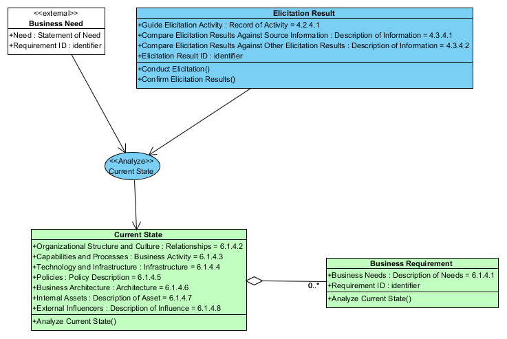
Figure 7:Analyze Current State Data Flow Diagram
Guidelines, Tools and Techniques diagram
This diagram shows the guidelines/tools and techniques for each task that is captured as an operation of the artifact. Figure 8: shows the guidelines/tools and techniques used by the Define Change Strategy operation.
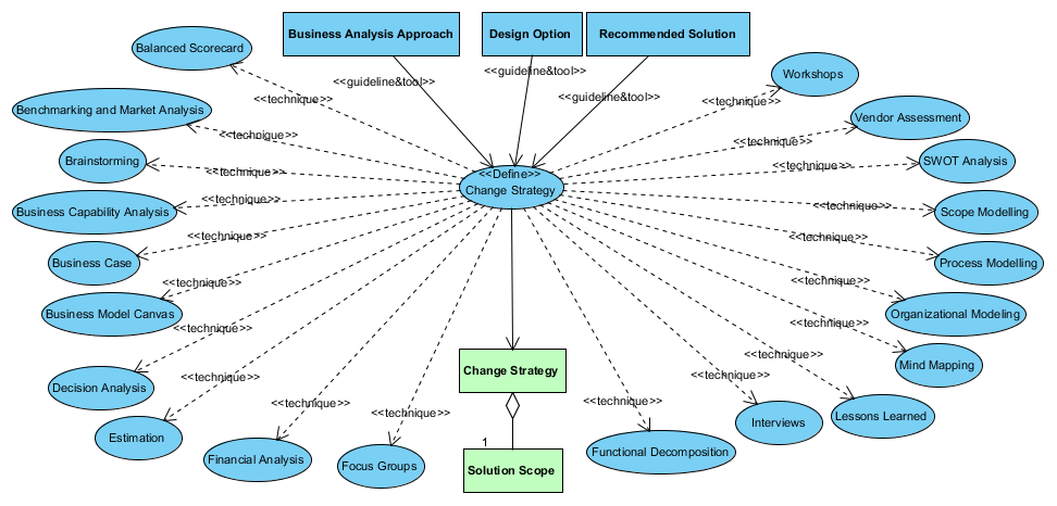
Figure 8:Guidelines, Tools And Techniques Used By Define Change Strategy
The Change Strategy operation impacts both the Change Strategy and the Solution Scope artifacts. The impacted artifacts are also shown on this diagram.
Stakeholders Diagram
The Stakeholders Diagram shows the stakeholders that contribute to a task (artifact operation). Figure 9: is an example showing the stakeholders that contribute to the Trace Requirements operation.
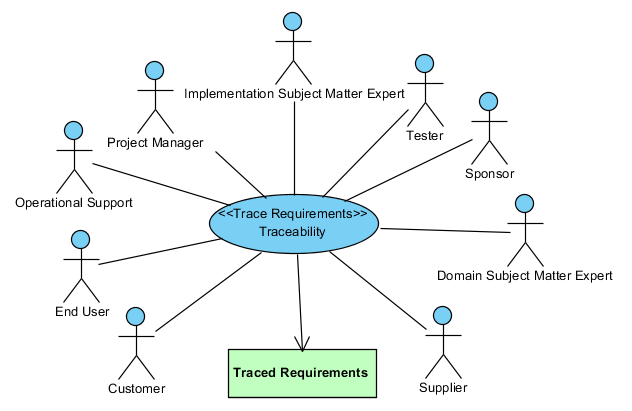
Figure 9:Trace Requirements Stakeholders
State Diagram
If an artifact includes more than 1 operation, I will also include a state diagram for that artifact. The state diagram shows the sequence of operations assigned to that artifact. Figure 10: shows the states that a Requirement goes through as each operation is executed.
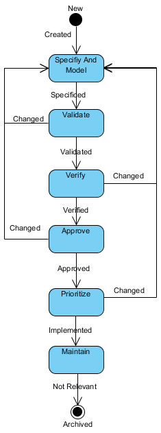
Figure 10:Requirement State Transition Diagram
When a requirement is created, it is being specified and modeled. When completely specified the requirement can be validated. When validated the requirement is verified. When verified, the requirement is approved. When approved the requirement is prioritized for development. When the requirement is implemented it is maintained until it is no longer relevant to the project. The diagram shows that a requirement may be changed between specification and implementation.
Properties
The modeling tool provides a properties sheet for every component in the model. One of the property fields is a description of the component. I use the description to capture the text from the BABOK as follows:
|
BABOK Text
|
Model Description Field
|
|
Knowledge Area description
|
Knowledge Area
|
|
Task Purpose
|
Task
|
|
Task Description
|
Task
|
|
Task Inputs
|
Relationship between the input artifact and the output artifact
|
|
Task Elements
|
Artifact attribute
|
|
Task Guidelines and Tools
|
Relationship between guideline and tool and the task
|
|
Task Techniques
|
Relationship between technique and the task
|
|
Task Stakeholders
|
Relationship between stakeholder and task
|
|
Task Outputs
|
Artifact
|
|
Technique: Purpose, Description, Elements, Usage Considerations
|
Technique
|
|
Key Concepts, Underlying Competencies, Perspectives
|
Equivalent component in the model
|
For example, BABOK section 3.1.6 describes the Brainstorming technique, when applied to the Plan Business Analysis Approach task as: “used to identify possible business analysis activities,
techniques, risks and other relevant items to help build the business analysis approach.”
In the model the same text is shown when the relationship between the Brainstorming technique and the Plan Business Analysis Approach task is selected and its description displayed.
Relationships to a model component are also displayed in the component specification. Therefore all text related to a component is accessible from that component’s specification.
Using The model
With all relevant information has been entered into the tool, I have created a consistent, unambiguous and complete model with no duplication.
See my document on BABOK Recommendations for a list of errors, omissions and ambiguities that I found while creating the model.
Where inputs and outputs are duplicated in the BABOK diagrams, the model consolidates these into a single set of relationships between artifacts.
In order to address questions about the BABOK information, I create a diagram and display the relevant components on that diagram. The tool automatically shows the attributes operations and relationships of those components. These are some examples of information that may be derived in this manner.
What Are The Elements Of Related Artifacts?
To show the artifact elements that are used to create an output artifact:
- create a class diagram
- place the artifact in question on that diagram
- place all related artifacts on that diagram (the tool informs you of the related artifacts)
- display the attributes of all artifacts on the diagram
Figure 11: shows all input elements of Business Analysis Information.
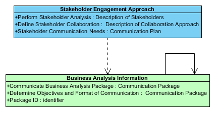
Figure 11:Business Analysis Information Inputs
Business Analysis Information is created from the elements from Stakeholder Engagement Approach and from other Business Analysis Information.
What Are The Dependencies Of An Artifact?
Not every artifact is needed for your project. If your project only needs a subset of those in the BABOK, a traceability tree diagram shows the elements that are needed in order to produce the artifacts included in your project plan.
I assume that the project plan captures the essential deliverables.
For example, suppose your only essential project deliverable is requirements. Figure 12: contains a traceability tree which shows the artifacts required to produce requirements.
I create this diagram by:
- creating a class diagram
- place the essential artifact on the diagram
- add all input artifacts to the diagram
- for all input artifacts, add all input artifacts to the diagram
- continue adding input artifacts until only external artifacts are added to the diagram
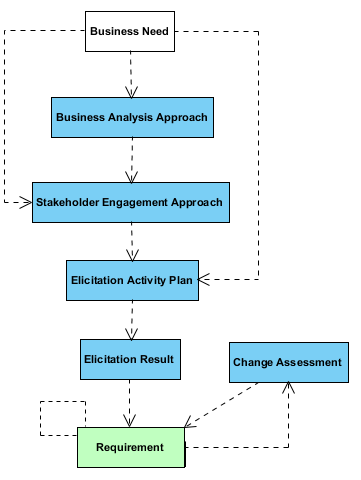
Figure 12:What Is Used To Produce Requirements
The resulting diagram shows that in order to produce a complete set of requirements, the BA will also need to create Elicitation Results, an Elicitation Activity Plan, a Stakeholder Engagement Approach, and a Business Analysis Approach. Business Needs are the only required external input to the project.
If changes are anticipated, then a Change Request artifact will also be defined.
The link from Requirement to itself indicates that requirements have a life-cycle.
What Is Required By A Task?
You are assigned to a task and wish to know everything about performing that task, in terms of inputs, stakeholders, guidelines, tools, techniques and elements.
Figure 13: shows everything involved with producing a Current State Description. To see the description of a component you simply click on the component and its text is displayed.
This is equivalent to the information contained in section 6.1of the BABOK.
To create this diagram I:
- duplicated the Guidelines/Tools and Techniques diagram
- added the stakeholders related to the task to the diagram
- added the inputs related to the output artifacts to the diagram
- displayed the artifact elements
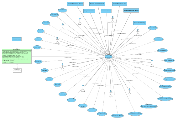
Figure 13:How To Derive A Current State Description
The labels on the relationships identify if a Guideline/Tool or a Technique is connected to the task. Yes, the diagram is not very readable in this format, but it serves a specific purpose for the BA and is not intended to be presented to external stakeholders. As the BA, you can organize this diagram in any manner that serves your purpose, even splitting the information over several diagrams.
This diagram duplicates the diagram shown in the Input subsection (6.1.3), but includes techniques, elements and stakeholders.
Where Is A Technique Used?
Consider the situation where you have expertise in a certain technique. As a member of the project team you may want to know where this technique is used.
As the data modeling expert, Figure 14: shows the tasks and artifacts that require my skills.
To create this diagram:
- a use case diagram is created
- the Data Modeling technique is added to the diagram
- tasks related to Data Modeling are added to the diagram
- artifacts that use Data Models are associated with the tasks on the diagram
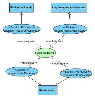
Figure 14:Where Data Modeling Is Used
Data modeling is used in the creation of Elicitation Results, Requirements and Requirements Architecture.
- Elicitation Results - used to understand entity relationships during elicitation
- Requirements Architecture - used to describe the requirements structure as it relates to data
- Requirements - used to identify data structure that may be similar across the enterprise in order to facilitate reuse, and used to model requirements to show how data will be used to meet stakeholder information needs
What Are The Responsibilities Of A Stakeholder?
Figure 1: contains the activities that a project manager contributes to. To produce this diagram:
- create a use case diagram
- place the stakeholder onto the diagram
- populate the diagram with all tasks from the Tasks package
- remove tasks that are not automatically connected to the stakeholder
Figure 1: shows that the project manager may be expected to contribute to as many as 18 tasks. (The actual number depends on which artifacts the project team decides that they will produce during analysis.)
Summary
The model was originally created to assist with my understanding of the BABOK. I find that extracting, analyzing and synthesizing information gives me a much better understanding than simply reading a 1-dimennsional narrative of the BABOK. However the major benefit comes into play when the BABOK is used as the basis for customizing your project plan. The BA should assist the project team with selecting the appropriate deliverable artifacts. By using the traceability diagrams the project can then decide what artifacts the BA is to produce as a means to achieving those deliverables. The data flow diagrams and guidelines, tools and techniques diagrams assist with identifying the work that will be required. A project plan can be derived from this information and stakeholder diagrams used to allocate resources to the plan.
References
The model of the BABOK was created using Visual Paradigm - https://www.visual-paradigm.com/
The BABOK model can be downloaded from OneDrive – https://onedrive.live.com/?id=316FA5CEAAEC5E2%21105&cid=0316FA5CEAAEC5E2
Learn more about the BABOK - https://www.iiba.org/standards-and-resources/babok/
Author: Leslie Munday, Sr. IT Professional
Leslie is a Senior level Information Technology (IT) professional with expertise in Business and Systems Analysis, Process Analysis, Requirements Analysis and Project Management.
Previously, I published a book titled “Analysis Through Pictures”. This book details the knowledge, skills, methods and best practices that I used as a systems analyst, up to 2011. It shows how the Rational Unified Process can be used effectively, to produce quality software systems. I have been actively involved with the International Institute of Business Analysis. I joined the IIBA after they asked me to give a presentation about traceability. Since then I have presented an analysis model of the Business Analysis Body Of Knowledge, and published several analysis presentations to various business analysis organizations. My website is intended to share my analysis knowledge skills and presentations with anyone who is interested in learning about the role of a business analyst.
Figure List