This article describes the Data Flow Diagram devised by Larry Constantine in the 1970s as part of the Structured Analysis movement. It follows logically from the Context Diagram article in which we used a much simplified Data Flow Diagram to show a proposed system in the context of its external interfaces and actors.
Introduction
The Data Flow Diagram (DFD) provides a graphical representation of the flow of data through a system. It shows logically what information is exchanged by our system processes and external interfaces or data stores, but it does not explicitly show when or in what sequence the information is exchanged.
Data Flow Diagrams are one of the three essential perspectives of the Structured Systems Analysis and Design Method (SSADM) that predates the more recent object oriented design methods and notations such as UML. This does not mean that the DFD has lost its usefulness even for new analysis endeavors, and any business analyst is bound to encounter them while reviewing the original design documentation for ‘legacy’ systems.
Diagram Elements
The diagram elements listed below and in the subsequent worked example are based on the Gane-Sarson symbol set (or notation) for Data Flow Diagrams. There are other symbol sets such as Yourdon-Coad, which comprise the same four element types albeit represented using different shapes.
|

|
This lozenge shape represents a system Process which typically consumes data from an Interface or Data Store (see below), transforms it in some way, and then feeds out the end result. to an Interface or Data Store.
|
|

|
This rectangle shape represents an external Interface, which is any external system or human actor that interacts with our system processes. In some alternative notations the Interface shape may be known as a Terminator, an Input/Output or an Entity.
|
|

|
A Data Flow line shows data flowing from a Process to an external Interface or Data Store, or data flowing from an external Interface or Data Store to a Process. The data flows in the direction of the arrow.
|
|

|
A Data Store may represent an entire database or a more specific entity within a database or other persistent data store.
|
While this table of diagram elements is informative, the only way to truly appreciate the role of the Data Flow Diagram is via a concrete worked example.
Worked Example
The figure below shows a Data Flow Diagram that was drawn in Microsoft Visio using the Gane-Sarson symbol set.
A good Data Flow Diagram should be easy to comprehend and intuitively obvious to the lay person; ideal for reviewing with non-technical project stakeholders. So take time to interpret the diagram yourself, and then read the description that follows.

This worked example DFD comprises five processes, four external interfaces / actors, and two data stores. It is not meant to be an exhaustive representation of the data flows in a banking system, but sufficiently comprehensive to give a good feel for how a DFD might be constructed
A Bank Manager actor provides New account details to the Open Account process which results in Customer details being persisted in the Customer Database data store and Account details being persisted in the Account Database data store. Although we have used the phrase ‘results in’ as part of this explanation, the DFD implies no such cause and effect; all it shows is that the Open Account process can read in data from the Bank Manager interface and write out data to the Customer Database and Account Database data stores in no particular order.
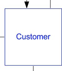
A Customer actor using the Online Banking Login process must provide some data in the form of a set of Login credentials such as a user name and password.
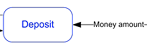
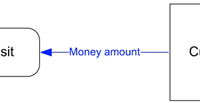
A Customer actor can receive a Money amount from the Withdraw process and can supply a Money amount to the Deposit process; in either case causing (although this causation cannot be explicitly modeled) an Account balance update to the Account Database data store.
A Customer actor can initiate the Transfer Funds process, to which he or she must provide an Account destination and money amount. The Transfer Funds process can send a Money amount to another bank via the Other Bank interface.
Just like the Customer actor, a Third Party actor can make use of the Deposit process (but obviously not the Withdraw process) by supplying a Money amount.
Tips and Tricks
Although our focus is on computer systems and software implementations, the DFD has wider uses in modelling non-computerised company processes and exchanges of information. The abstract symbol set could be used to model manual processes and physical data stores such as a filing cabinet. But we’re computer analysts, right?
Data flows between external interfaces and data stores should not be shown, for the simple reason that these are considered to be external and ‘out of scope’. The analyst should have no knowledge of the interconnections between external entities.
Notice how in the worked example, when modeling the data flow from the Customer to the Login process we chose to label the data flow with the phrase Login credentials rather than (for example) username and password. This gives us some flexibility in defining elsewhere what the required login credentials are without invalidating the diagram. In the future we may require the customer to supply an email address and PIN in order to log in. Note, however, that this is a personal preference and some analysts may prefer to be absolutely explicit when labeling data flows.
The external interfaces and actors in this DFD correspond with those shown on the Context Diagram in the previous article, so all we have really done here is to decompose the all-encompassing Bank System process from the Context Diagram into a set of internal processes for specific tasks. We have defined these processes with a view to making each one a discrete use case on a UML Use Case Diagram, with each data flow between an Interface and a Process in this diagram suggesting an association between an Actor and a Use Case. This is not obligatory and is merely a suggestion for aiding traceability between the various systems analysis diagrams and artifacts.
The DFD might also drive the creation of another UML diagram: the UML Activity Diagram which would show the order in which the Processes -- to be re-branded as Activities -- would be performed. This would resolve the problem of the DFD show what data is exchanged but not when.
Next Stop: the Entity-Relationship Diagram
The Data Flow Diagram focuses on the data that flows between system processes and external interfaces, and alludes to the fact that some data are persisted in data stores. The data store that has ‘persisted’ (pun intended) for longest, i.e. has stood the test of time, is the relational database. So in the next article we’ll look at how to model a relational database structure using an Entity-Relationship Diagram.
Author : Tony Loton - Author & Self-Publisher
As a former IT consultant and consultancy practice manager, Tony has published many IT feature articles and books including the most recent "UML Software Design with Visual Studio 2010"