About the Series
This series of articles is designed to present the set of core UML diagrams in a way that emphasizes the important relationships between the different diagrams and the logical progression from one diagram to another.
In this installment we progress from the UML State Diagram to the UML Component Diagram.
Introduction
The UML Component Diagram along with the complementary UML Deployment Diagram shows how a software solution will be delivered and deployed in the form of interconnected components that interoperate via well-defined interfaces. You can think of this as analogous to how electronic components are wired together, and in this context you should consider that any one component may be replaced by a different but compatible component with no adverse effect.
Diagram Elements
The number and type of diagram elements will vary according to the UML diagramming tool, the version of UML, and the context in which the diagram is to be used. Our subsequent worked example will utilize the following diagram elements that should be available in most if not all UML tools.
 |
A Component is a deployable and replaceable unit of software deployment that commonly takes the form of an executable .exe file, a Java Archive (JAR) file, or a .NET Assembly DLL. |
|
 |
An Interface is a lollipop shape that represents a limited set of functions via which one component may access the functionality provided by another component. The interface hides a component’s internal implementation. |
|
 |
A dashed Dependency line with an arrow shows that one component is dependent on – or makes use of – functionality provided by another component via one of the exposed interfaces. |
While this table of diagram elements is informative, the only way to truly appreciate the role of the UML Class Diagram is via concrete worked examples.
Worked Example
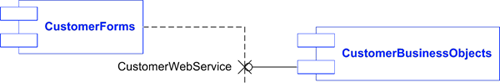
The following worked example of a UML Component Diagram shows how our running “Banking” example might be organized as a set of interconnected deployable components. It reflects the arrangement of classes into packages that was devised in the earlier UML Class Diagram article.
In this scheme the CustomerForms component depends on a CustomerWebService interface that is exposed by the CustomerBusinessObjects component and which hides the internal implementation of the component. Similarly, the BankingForms component depends on a BankingWebService interface that is exposed by the BankingBusinessObjects component.
The Controllers component is dependent on both the CustomerBusinessObjects and the BankingBusinessObjects components through their respective interfaces.
The Controllers component is dependent on (or at least some of its contained classes are dependent on) the CustomerForms component, because the controller classes launch those forms. Similarly the Controllers component is dependent on (or at least some of its contained classes are dependent on) the BankingForms component
As hinted in the previous paragraph, components will contain object classes. It is usual for UML modeling tools to provide a mechanism for mapping classes onto the components, like this:
It shows that the Bank, BankAccount, CheckingAccount and SavingsAccount classes are mapped to the BankingBusinessObjects component for deployment. The other classes will be mapped to different components for deployment.
Tips and Tricks
In the UML Use Case Diagram article I explained how UML stereotypes could be used to distinguish different usages of the same UML shape. The UML component shape may be stereotyped in order to distinguish, for example, between <<executable>> components (which are typically .EXE files) and <<library>> components (which may typically be Windows DLLs) as shown below.
The worked example presented in this article represents only one way to skin the component-design cat for our running case study. As you will see when we consider the UML Deployment Diagram below, it might turn out to be better from an architectural standpoint to map subsets of the controller classes onto two separate controller components: one for the CustomerControllers and another one for the BankingContollers. Alternatively, these controllers might be mapped to the CustomerForms and BankingForms components on which they depend.
You might also think about incremental delivery whereby some software components may be usefully deployed before other are ready – for example the customer management components before the banking components – and in this respect the original packaging of use cases may help to drive the packaging of components.
The worked example utilizes the “façade” design pattern that hides multiple server-side object classes behind a smaller number of simple interfaces… which in a modern distributed software solution I have assumed will be implemented in the form of web services. While the software analyst has probably done all that needs to be done, and maybe even too much at the high level, the technical architect would need to do some lower-level work in defining the couplings between the implementation classes and their facades.
The UML Component Diagram in general (and this component diagram in particular) leads logically to the UML Deployment Diagram which demonstrates how the various components may be actually deployed to nodes representing the client and server computers. Here is an example:
Notice how the components are deployed in a client-server arrangement, with two client computer types – CustomerClient to run the customer management application and BankingClient to run the banking application – connected via an intranet or the Internet to a single BankServer that hosts both ‘business’ components.
Notice also how an identical Controllers component must be deployed to both client computers because of the dependencies set out on the component diagram. This may highlight a potential design error, so – as suggested earlier – you might go back and revisit the mapping of all controller classes onto a single component; maybe by mapping the customer-specific controller classes to the CustomerForms component and mapping the banking-specific controller classes to the BankingForms component.
From the analyst’s perspective, the UML Deployment Diagram warrants no further explanation.
Author: Tony Loton, Author
Tony Loton has authored and co-authored the books “Professional UML with Visual Studio .NET”, “Professional Visual Studio 2005 Team System”, and “UML Software Design with Visual Studio 2010”