Across multiple industries, systems exist to automate manual tasks for users. To that end, any process within a system will take data in, sort it in a useful way, and then return that data as output. Data flow diagrams are ideal for depicting these type of scenarios—they help viewers visualize and understand data stores, data flows, and business processes. A data flow diagram (commonly abbreviated to DFD) shows what information is needed within a process, where it is stored, and how it moves through a system to accomplish an objective. As its name implies, a data flow diagram depicts the flow of data within a system.
BABOK 2.0 has an entire section dedicated to data flow diagrams, noting that data flow diagrams “show how information is input, processed, stored, and output from a system.” [1] Wikipedia puts it this way: A data flow “is a graphical presentation of the ‘flow’ of data through an information system.” [2] Although it displays the flow of data, a data flow diagram is different from a flowchart in that it excludes cause and effect, sequences and the order of the process.
Additionally, data flow diagrams are typically user-friendly, and easy for designers and end-users alike to interpret. As such, they are useful in both the discovery and development stages of a project. While data flow diagrams are common to many organizations, some analysts may know them by another name. As Yourdon notes in his article on structured analysis, certain organizations or business cultures refer to data flows diagrams as “Bubble chart, Bubble diagram, Process model (or business process model), Business flow model, Work flow diagram, or Function model.” [3]
Data flow diagrams are usually classified in different numerical levels in order to display more granular levels of a business process, with level 0—also known as a context diagram—being the highest level. Level 1 is the next highest level view of the information flow; 2 is more granular than 1; 3 is more detailed than 2, and so on (though few systems display more than 3 levels). This method is particularly helpful with complex business processes since it enables a business analyst to illustrate an entire business process succinctly, and to get as detailed as necessary. According to one site, “The technique exploits a method called top-down expansion to conduct the analysis in a targeted way.” i Therefore, if a user has many processes and levels of data to include in a diagram (subprocesses), the multi-level process should be used. In these cases, each diagram (subprocess) should have a unique identifier. The multi-level aspect of data-flow diagrams eliminates any need for an analyst to depict hundreds of processes or pieces of data. Multiple processes within one level may be organized by using numerical identifiers such as 1.0., 1.1, and so on. It is also helpful to use broad categories rather than minute details to cover the business processes. For example, minor bits of deviating information, such as error messages, would likely not be useful to include in a data flow diagram. The practice of keeping DFDs simple and separated into different sublevels is particularly helpful in the agile development process where many of the processes may change frequently. Also particularly useful to the agile process, iterations of data flow diagrams may be archived to show the history of a project’s development as new discoveries and business needs dictate changes to a system’s information sources, outputs, and flow.
For an analyst constructing a level 1 DFD, it may be helpful to start with a context diagram, which is also known as a level 0 data flow diagram. According to Wikipedia: “The context diagram shows the entire system as a single process, and gives no clues as to its internal organization.” This will enable the user to quickly isolate the main entities, inputs, and outputs. Here is an example of a context diagram, or level 0 data flow diagram:

What elements does a data flow diagram include?
A data flow diagram includes the data, processes, stores, and external entities of a system, and all of the data necessary for the system to function (both how it flows and where it is stored). To that end, it includes notations (or symbols) from one of two traditions: Yourdon & Coad or Gene & Sarson. For a visual comparison of the Yourdon & Coad and Gene & Sarson symbols for these, please see this link. (Note that while both are correct, Yourdon & Coad symbols are generally more commonly used in the business analyst profession.) These traditions are just two different styles of symbols, but both depict the same things: processes, datastores, dataflows, and external entities. The style of symbols an analyst follows is not as important as consistently following that style. The computer software program at an analyst’s disposal may dictate that one type of notation is easier to create and edit than another. A brief overview of each of a data flow diagram’s components follows.
Process. A process is also commonly referred to as “a bubble, a function, or a transformation.” [4] Its function is to “transform an incoming data flow into an outgoing data flow.” [5] In other words, a process is how information moves along in the system. A process should be named according to precisely what it does (i.e., Get orders), and it should have inputs and outputs (dataflows, described below). Processes with no information flowing in to or out of them are known as “infinite sinks” and are logically inconsistent. [6]
Below is an example of Yourdon & Coad process symbols.

Dataflows. Dataflows show how information moves along within a system; they are “pipelines” through which bits of data flow. [7] Flows represent “data in motion, whereas the stores . . . represent data at rest.” [8] In both symbolic schools, dataflows are presented as arrows and labeled according to the data they represent (i.e., Record purchase). Examples are below.

Datastore. A datastore is a storage place for data that is used within the system. A datastore can be anything from a database to a customer (either of which can hold customer attributes that the system must extract). According to Yourdon, “Typically, the name chosen to identify the store is the plural of the name of the packets that are carried by flows into and out of the store” [9] (i.e., Purchase). Below is an example from the Yourdon & Coad school.
 Yourdon & Code datastore symbol
.
External entities. External entities are outside sources and targets of information that are relevant to the system. Examples of external entities could be customers, suppliers, or external databases. The Yourdon & Coad school uses a box to represent external entities.

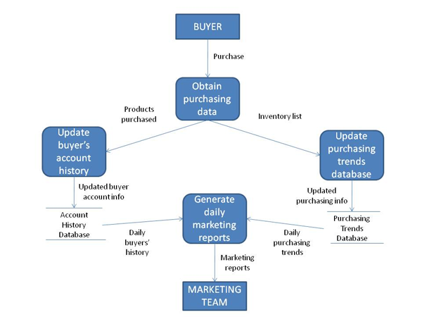
When all of the data flow elements are combined into one diagram using Yourdon & Coad symbols, here is just one example of what the final piece might look:

What does a data flow diagram not include?
-
Procedures. A data flow does not answer procedural questions that flowcharts usually cover. For example, a data flow diagram representing an order delivery system would not depict whether orders were taken in person or virtually, or whether they happened automatically or manually.
-
Sequences. A data flow does not represent what happens first or second, or the order in which a process runs.
-
Users. To quote BABOK, a data flow diagram “cannot easily show who is responsible for performing the work.” The owner of a particular process is not relevant to a data flow diagram.
-
Alternative scenarios. A data flow diagram follows one main path of information, and does not take into account a series of feasible spin-off scenarios, such as a flow-chart might.
As a matter of proper use, a data flow diagram also should not include dozens of entities, stores, and flows. According to Yourdon, “each DFD figure should have no more than half a dozen bubbles and related stores.” [10] If a diagram seems particularly complex (representing a complex system), it must be broken into levels, meaning an analyst first depicts the most basic aspects of the system in one simple data flow diagram. Once that diagram is logically depicted, succeeding levels are created, each representing more complex aspects of the system. For more details on successfully constructing levels of data flow diagrams, please see Yourdon’s article here.
While not applicable to all business scenarios, data flow diagrams are almost always ideal tools for analysts who wish to analyze or depict the extent of information needed for a system, where that information will be stored, and how it will move throughout the system. Used properly, they are a potent tool in an analyst’s arsenal.
Author : Morgan Masters is Business Analyst and Staff Writer at ModernAnalyst.com, the premier community and resource portal for business analysts. Business analysis resources such as articles, blogs, templates, forums, books, along with a thriving business analyst community can be found at http://www.ModernAnalyst.com
[1] A Guide to the Business Analyst’s Body of Knowledge® (BABOK® Guide), Version 2.0, International Institute of Business Analysis, Toronto, Ontario, Canada, ©2005, 2006, 2008, 2009.
[2] http://en.wikipedia.org/wiki/Data_flow_diagram
[3] “Data Flow Diagrams,” from the Structured Analysis Wiki. http://www.yourdon.com/strucanalysis/wiki/index.php?title=Chapter_9
[4] ibid
[5] Data Flow Diagram Notations
[6] ibid
[7] ibid
[8] ibid
[9] ibid
[10] ibid
[11] http://www.getahead-direct.com/gwbadfd.htm