This article describes the Entity Relationship Diagram that allows you to document the structure of a database in terms of persistent entities and the relationships between them.
Introduction to ERDs
The Entity-Relationship Diagram (ERD) provides a way of graphically representing the logical relationships between entities in order to create a database schema to persist those entities.
The Entity-Relationship Model was first proposed by Peter Chen of Massachusetts Institute of Technology (MIT) in the 1970s. You will see later how Chen’s own notation for Entity-Relationship Diagrams produces diagrams that are more verbose and cluttered than the diagram presented herein which uses the alternative Crow’s Foot notation taken from SSADM and other design methods.
Diagram Elements in ERD
The diagram elements listed below and in the subsequent worked example are based on the Crow’s Foot Notation supported by the Microsoft Visio Database Model Diagram. You will read later how an Entity-Relationship Diagram may be drawn in other modeling tools using the alternative ‘Chen’ notation.
 An persistent Entity, which usually maps to a table in the underlying database, is represented as a rectangle containing Attributes that map to table columns or fields. An Entity is something that has an independent existence and which can be uniquely identified.
 An Attribute is a named property of an Entity that stores some value. Attributes may be required (shown bold) and may be designated as primary (PK) or foreign (FK) keys in the underlying database table.

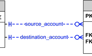
A Relationship line shows that one Entity is related to another one because the underlying database tables are linked via a primary key / foreign key agreement. Symbols at the ends of the relationship line are used to show the minimum and maximum numbers of each Entity that participate in the relationship, for example -H------O< meaning "one to zero or more". Where two Entities are connected by more than one relationship, a role name (e.g. source_account) can be used to distinguish the relationships.
The cardinality of relationships deserves some further explanation:
-H---- or ----H- (double line) means mandatory one
>I---- or ----I< (line and crow’s foot) means mandatory many.
-IO---- or ----OI- (O and line) means optional one.
>O---- or ----O< (O and crow’s foot) means optional many.
While the table of diagram elements is informative, the only way to truly appreciate the role of the Entity-Relationship Diagram is via a concrete worked example.
Worked ERD Example
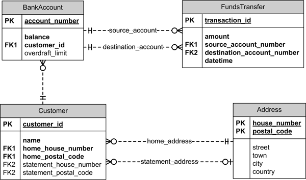
The figure below shows an Entity-Relationship Diagram that was drawn in Microsoft Visio as a Database Model Diagram using the Crow’s Foot Notation. Try to interpret the diagram yourself and then read the description that follows, keeping in mind that this diagram is not meant to be an exhaustive representation of the problem domain being modeled.

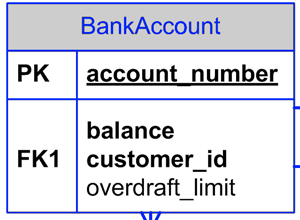
A BankAccount entity is uniquely identified by the account_number primary key attribute. It has a required balance attribute (because an account must have a balance) and an optional overdraft_limit (because not all accounts have an overdraft facility). The BankAccount has a customer_id foreign key attribute that identifies the account customer via the relationship to the Customer entity.
Two BankAccount entities can participate in a funds transfer represented by the FundsTransfer entity. A FundsTransfer must link to two accounts which take the roles of the source_account and destination_account, but any given account can participate in any number of funds transfers.
A FundsTranfer is uniquely identified by the transaction_id primary key attribute. It has a required amount attribute (because every funds transfer must be of an amount) and a required datetime attribute (because each transfer must be timestamped). The source_account_number and destination_account_number foreign key attributes identify the two BankAccounts of the two relationships.
A Customer is uniquely identified by the customer_id primary key attribute, and each customer has a required name. A customer has two pairs of attributes labeled as FK1 (foreign key 1) and FK2 (foreign key 2) that link to to possible Addresses for the customer as indicated by the relationships:
The home_address relationship which is identified by the FK1 pairing of home_house_number and home_postal_code is mandatory since every customer must have a home address on file.
The statement_address relationship which is identified by the FK2 pairing of statement_house_number and statement_postal_code is an optional additional address to which the account statements may be sent.
There is no unique identifier for an Address entity, but the combination of house_number and ,postal_code attributes uniquely identifies any address -- thus forming a composite key. This composite key PK1 is the counterpart of the foreign keys FK1 and FK2 in the Customer entity. Note that this use of composite keys has been contrived for illustration only and should not be treated as an example of good database design.
ERD Tips and Tricks
Note that while the E-R diagram looks superficially similar to a UML Class Diagram, there are some important differences. For example: whereas a UML class representation contains no explicit linking attributes, the E-R identifies keys that link together instances of the various entity types. Furthermore, the E-R linkage is in what might be considered to be the opposite sense. Where a Customer object (in UML parlance) would hold an array of references to the customer’s BankAccounts, in an E-R diagram the same one-to-many linkage is effected by many BankAccount entity instances holding foreign keys to their Customers. Further discussion of this translation of concepts known as object relational mapping is beyond the scope of this article.
An Entity-Relationship diagram represents the logical (but not necessarily physical) structure of a relational database. Although not mandatory, it is usually a good idea to ensure that the logical structure is fully normalised so that redundant data is reduced or eliminated. Our worked example is only partially normalised. For example: the Address entity has been factored out as separate from the Customer entity (which is good) but the Customer entity includes a name attribute which should be separated out as (at least) two attributes for the first_name and last_name so as to be properly normalised.
The worked example in this article was devised using the Crow’s Foot Notation that is used in SSADM and some other design methods. As hinted throughout, the main alternative notation is the one that was devised by Peter Chen and which is illustrated (partially) below. While the Chen notation benefits from showing relationship roles and entity attributes separately and explicitly, the non-concise nature of the notation tends to produce cluttered diagrams.

One advantage that Chen’s notation has over the Crow’s Foot notation is the ability to adorn relationships (FundingSource and TransferDestination in the diagram above) with their own attributes, rather like association classes on a UML Class Diagram. When not using the Chen notation it is possible -- indeed necessary -- to devise additional entities to encapsulate the collection of attributes required on each relationship.
Summary
The Entity-Relationship diagram provides an industry-recognised way to model the logical structure of a relational database.
Related Data Modeling articles:
Putting Systems Analysis “Into Context” using the Context Diagram
Data Flow Diagram with Examples & Tips
Author : Tony Loton - Author & Self-Publisher
As a former IT consultant and consultancy practice manager, Tony has published many IT feature articles and books including the most recent "UML Software Design with Visual Studio 2010"