A.1 The Vision Statement
The vision statement is captured within a vision document and is a high-level overview of the purpose of the project and its purpose in improving the business [1].
I run a successful restaurant in the business area of a large city. It is a very nice restaurant with high-class clientele and excellent food.
In the evenings we hire only the best staff and prepare the best food in its class.
During the day, we entertain all sorts of riff-raff from the area. These customers require fast food of average quality and the minimal service that satisfies their needs for a good lunch; ordered from our cut-down menu of smaller plates organized by categories. During the day we clear the restaurant of its fixtures to allow for more tables with the purpose of serving as many customers in as short a time as possible. The lunchtime customers do not require excellent waiter service, and so we employ cheap unskilled labour to wait the tables. As a result the lunchtime waiters, although cheap, make too many mistakes and are not to be trusted. The aim of this effort is to eliminate lunchtime wait staff to the largest extent possible, while satisfying customer needs, and replace them with an automated system suitable for ordering fast food from our excellent kitchens.
A.2 Business Model
The business model describes the business as it is today.
A.2.1 Business Architecture
The business architecture diagram shows the various departments of the business and the interactions between them.
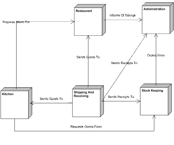
Figure 1: Business Architecture Diagram
Restaurant department is responsible for everything to do with serving customers. This includes:
· Assigning tables,
· Showing customers to an assigned table,
· Holding customer belongings while in the restaurant,
· Serving food,
· Clearing tables,
· Billing customers.
The kitchen is responsible for all food related activities of the restaurant, including:
· Determining the menu items,
· Preparing food,
· Stocking ingredients,
· Washing and cleaning kitchen and restaurant utensils.
Shipping and Receiving is responsible for incoming and outgoing restaurant items. These include:
· Receiving food for the kitchen,
· Receiving items for the restaurant,
· Handling receipts for received items,
· Garbage collection.
Stock Keeping is responsible for maintaining restaurant supplies. These include, managing kitchen stocks and ordering necessary items.
The Administration department is responsible for handling all incoming and outgoing restaurant finances. It receives receipts for bills from Shipping and Receiving, orders for items from Stock Keeping and receipts for taking from the Restaurant.
A.2.2 Business Use Cases
The following use cases are derived from the business vision and verified by the business stakeholders that they capture the scope of the vision. Actors are those roles gaining ‘benefit' [2] from the business use case.
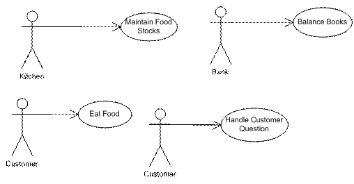
Figure 2: BUC Diagram
The above diagram does not contain a complete set of use cases, but includes those necessary to capture the functionality of the vision statement. All of the above use cases are candidates for automation.
Maintain Food Stocks – This use case is concerned with ensuring that the restaurant is properly stocked with food supplies. The Kitchen receives benefit from this use case.
Balance Books – This use case describes how finances are handled by the restaurant. The restaurant’s Bank receives benefit by ensuring that the restaurant remains solvent.
Handle Customer Requests – This use case handles complaints, queries and any general questions from a customer. The Customer is the actor receiving benefit from the use case.
Eat Food – This use case is concerned with seating, serving and billing the customer. The Customer is the actor receiving benefit from this use case.
A.2.3 Business Use Case Activity
The following activity diagram shows the steps of the BUCs, the workers that perform each step and the business objects that are manipulated by each step.
For the purposes of this exercise, it has been determined that only the ‘Eat Food’ BUC needs to be detailed.
A.2.3.1 Eat Food Business Use Case Activity
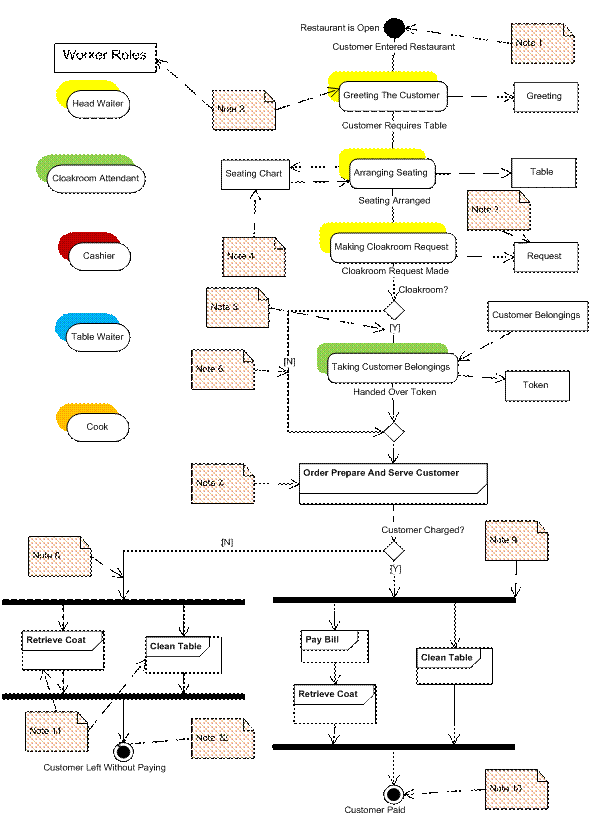
Figure 3: Eat Food BUC Activity Diagram With Business Objects
Notes:
Note 1 – This is the initial state ‘Restaurant Is Open’ (to customers) and the triggering event ‘Customer Enters Restaurant’ exits this state.
Note 2 – There are many ways that you may indicate the workers of each action in your activity diagram, without the use of swimlanes. These include adding stereotypes to the actions. (I.e. adding a waiter stereotype would indicate that this is a ‘waiter’ type of action.) In Figure 3: I have used color to indicate which worker performs what action.
Note 3 – Notice that every action includes an output flow to an object. You might argue that a ‘Request’ or a ‘Greeting’ is not an artifact, but when we start modeling the application we may discover that this was a useful object to capture.
Note 4 – The seating chart is changed by the head waiter and as a result the table object has its status changed from ‘Open’ to ‘Occupied’.
Note 5 – Try and make decisions into questions with Boolean answers (‘Y’ or ‘N’). It makes the activity diagram easier to maintain.
Note 6 – This is an example of an alternate workflow. Notice that the flow begins with a decision and ends with a merge. The decision asks the question, does the customer wish to make use of the cloakroom?
Note 7 – An example of an activity. In this instance the activity is being used to indicate that there are a lot of missing actions here. They are captured by the Order, Prepare and Serve Customer use case fragment [3].
Note 8 – This is an example of an extended flow. We know that it is an extension to the use case, because it does not return to the basic flow.
Note 9 – This is an example of a fork. Notice how more elegant this notation is than trying to describe this activity with text.
Note 10 – This is the successful postcondition.
Note 11 – Retrieve Coat and Clean Table are use case fragments that are ‘included’ in the flow of this use case.
Note 12 – A non-successful postcondition.
A.2.3.2 Order, Prepare And Serve Customer use case Fragment
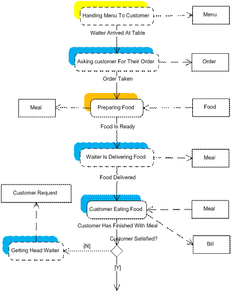
Figure 4: Order, Prepare And Serve Customer Activity
A.2.4 Business Objects
Business objects describe the artifacts that are manipulated by the business by normal business practices.
The objects that have been identified from the BUC activity diagrams are placed as business objects on a business objects diagram.
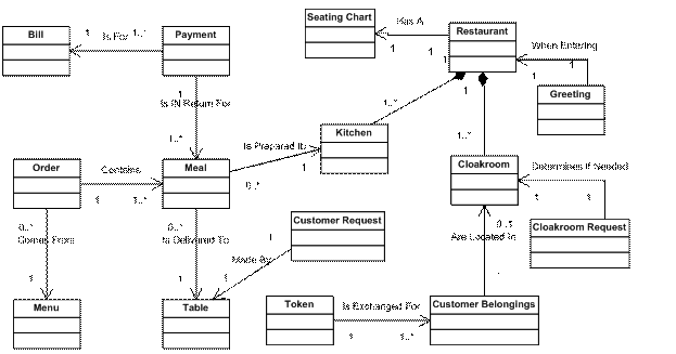
Figure 5: The Business Objects Diagram
- Bill – A request for the customer to pay the cashier the amount indicated.
- Cloakroom – Where a customer’s belongings are stored for the duration of their stay in the restaurant.
- Cloakroom Request – An inquiry as to whether the customer wishes to make use of the restaurant’s cloakroom to stow their belongings.
- Customer Belongings – That are exchanged for a cloakroom token.
- Customer Request – A request for restaurant assistance from a customer.
- Greeting – A welcome message to a customer entering the restaurant.
- Kitchen – Where food is prepared.
- Meal – Food served to a single customer at a single seating.
- Menu – What the customer uses to order food.
- Order – A combination of items from the menu for a single table.
- Payment – Money handed to the cashier.
- Restaurant – Where food is served to customers.
- Seating Chart – Displays which tables are reserved and which are free, as well as their size and location in the restaurant.
- Table – Reserved for customers in order that they may be served food.
- Token – A unique identifier for customer items in the cloakroom.
A.3 Candidate Use Case Model
This is a throwaway model (i.e. it is not necessarily maintained) used to show how the business activity is to e automated for the project.
The following actions have been extracted from the BUC activity diagram as candidates for automation.
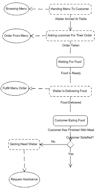
Figure 6: Candidate Use Case Activities
Candidate use cases have been added to the activity diagram to indicate where automation is anticipated.
A.3.1 Candidate Use Cases
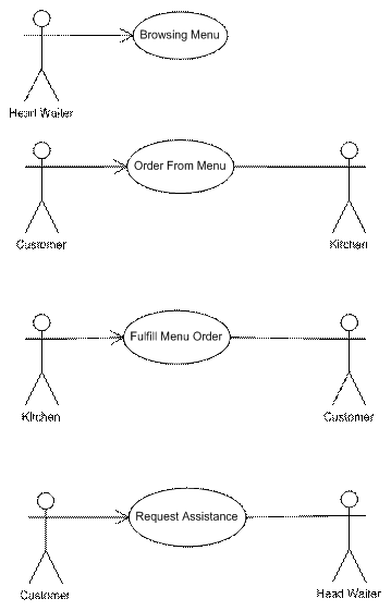
Figure 7: Candidate Use Case Diagram
The CUCs have been placed on a use case diagram and actors [4] have been added.
A.4 Application Model
The application model contains diagrams that capture the functionality of the application.
A.4.1 Application Deployment Diagram
The deployment diagram describes the existing [5] architecture to which the project will be deployed.
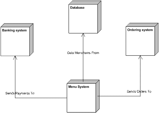
Figure 8: Menu System Deployment Diagram
The ‘new’ menu system interfaces with 3 other systems.
- For future release (Each time a payment is accepted by the system, the banking system is updated with the amount received.)
- Menu items and menu categories are selected from the system database. These are updated through the database entry screen, (which is not within the scope of this project).
- For future release (The menu system needs to inform the ordering system of food items that have been served to customers.)
A.4.2 Application Use Cases
The candidate application use cases have been condensed into 3 use cases that will be implemented for the first release of the product.
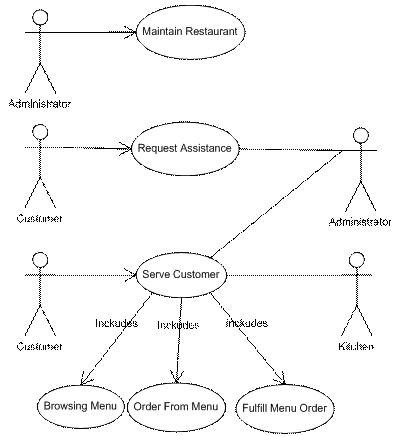
Figure 9: Application Use Cases Diagram
Figure 8: shows that the Browsing Menu, Order From Menu and Fulfill Menu Order CUCs representing steps in the BUC, have been realized by the Serve Customer AUC.
The Maintain Restaurant use case was added at the request of the head waiter in order to be able to add or remove tables for lunch seating.
- The Request Assistance use case allows the customer to ask for ‘human’ help.
- The Serve Customer use case is concerned with allowing the customer to order a meal from the restaurant menu.
- The Maintain Restaurant use case is concerned with of the restaurant layout.
A.4.3 Serve Customer Use Case Activity
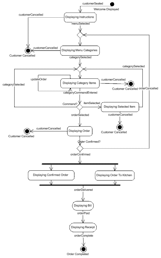
Figure 10: Serve Customer Activity Diagram
Use Case Description
The customer is seated at a table and the menu instructions are displayed. The customer selects menu items from menu categories until ready to order. The system displays a running total of selected items. When satisfied, the customer may order their meal. The kitchen is sent the order. The meal is prepared and delivered to the customer, who is then billed for their order. Once the meal is paid for the customer receives a receipt and the system is reset for the next customer.
Customer – The customer initiates the use case by selecting the menu system.
Kitchen – Provides the customer’s order.
The system is available, with the ‘Welcome’ screen displayed.
1. New customer is selected [6]
2. The system displays the menu instructions
3. Menu is selected
4. The system displays the menu categories
5. The customer selects a menu category
6. The system displays the category menu items
7. The customer adds and removes menu items from the category until order is selected
8. The system displays the customer order
9. The customer confirms the order
10. The system displays the confirmed order (with total cost) and displays the order to the kitchen
11. The head waiter confirms that the order is delivered
12. The system displays the bill to the customer
13. The head waiter confirms that the bill is paid.
14. The system displays the receipt
15. The customer requests a printout of the receipt
16. The system prints the receipt
The use case ends
A.1 Display more categories
17. At step 7, the customer selects a different category
18. The system displays the selected category menu items
The use case continues from step 7
A.2 Display menu item
19. At step 7, the customer selects a menu item to display
20. The system displays the menu item description
21. The customer selects a menu category
22. The system displays the selected category menu items
The use case continues from step 7
A.3 The customer cancels the order
23. At step 9, the customer cancels the order.
The use case continues from step 4
E.1. The customer does not complete the order
24. At step 2,4,6,8,18,20,22, the customer is cancelled
The use case ends.
1. The customer is served and the Welcome screen is displayed.
2. The customer is cancelled and the Welcome screen is displayed.
Object Descriptions
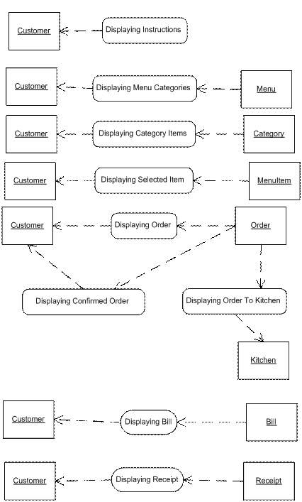
Figure 11: Serve Customer Impacted Objects
Customer – Represents a unique table seating at anytime the restaurant is open to customers.
Menu – Menu front page and a list of categories available to the customer.
Category – A list of menu items that are available to the customer.
MenuItem – A description of a menu item.
Order – A list of menu items that have been selected by a customer.
Kitchen – A display to the staff that prepare the order.
Bill – An itemized cost of the order.
Receipt – A display of the paper receipt that is given to the customer, in return for payment for the order.
A.4.4 Request Assistance Use Case
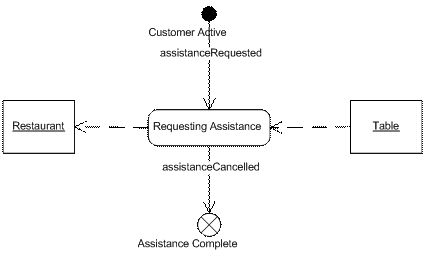
Figure 12: Request Assistance Use Case Activity
Use Case Description
This use case allows to customers obtain personal assistance from an employee of the restaurant.
Customer – Represents the table requesting assistance.
Restaurant – The restaurant staff that are informed of the request.
A customer is active at the table.
1. The customer selects assistance required.
2. The system displays the associated table to the head waiter.
3. The head waiter cancels the assistance call.
The use case ends.
None.
None.
The system displays the menu screen.
Object Descriptions
Restaurant – An employee of the restaurant responsible for maintaining the restaurant.
Table – The customer table requesting assistance.
A.4.5 Maintain Restaurant Use Case Activity
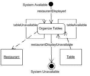
Figure 13: Maintain Restaurant Activity
Use Case Description
This use case allows the restaurant staff to add or remove tables on the restaurant menu seating chart.
Head Waiter – Person with the ability to organize the restaurant.
None.
The system is active
1. The system displays the restaurant layout to the head waiter.
2. The head waiter makes an available table unavailable, or an unavailable table available.
3. The system becomes unavailable.
The use case ends.
None.
None.
The system is unavailable.
Object Descriptions
Restaurant – A representation of the tables laid out in a restaurant seating plan.
Table – A selectable representation of a table in the restaurant seating plan.
A.4.6 Context Diagram
This is a condensed version of the system and use case diagrams, showing the interfaces with the system.
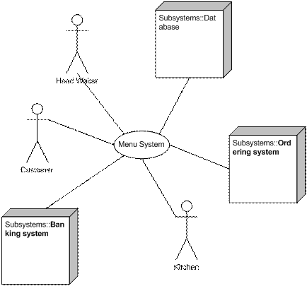
Figure 14: Menu System Context Diagram
A.5 Analysis Model
The analysis model confirms the completeness and correctness of the use case model.
A.5.1 Application Classes
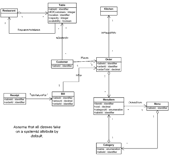
Figure 15: Restaurant System Class Attributes Diagram
The following classes breakdown the system requirements into groups of related functionality.
- Bill – Is concerned with billing the customer. A bill is specific to a bill for a table and has an amount.
- Category – Is concerned with organizing the menu items into categories. A category is identified by its name and the table that it is being displayed at. (The same category may be displayed at many tables.)
- Customer – Represents functionality that may be performed by people at an active table. The customer(s) are identified by the table they are seated at.
- Kitchen – Represents functionality performed by the kitchen. There is only the one kitchen.
- Menu – Represents the display of instructions and categories to the customer. The menu is identified by the table that it is displayed at.
- MenuItem – Represents the information and functionality around orderable menu items. Each menu item has a unique name within its category. The menu item has a description and a cost. It is identified by the table that it is being displayed at.
- Order – Represents the functionality concerned with placing an order with the system. The order is specific to a table at a specific time period. The order contains many menu items, which have a total amount, captured by the order.
- Receipt – Represents the confirmed receipt of a payment. The receipt is a direct response to a bill being paid.
- Restaurant – Represents the restaurant layout plan.
- Table – Represents an available restaurant space for a customer. Each table has a unique identifier, a location in the restaurant, a customer capacity, records the number of customers currently assigned to the table, and whether it is available or not.
A.5.1.1 Bill States and Transitions
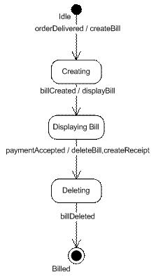
Figure 16: Bill State Transition Diagram
A bill is created when an order has been delivered. The bill is simply displayed to the customer and deleted once it has been paid. Deletion of a bill creates a receipt for the bill.
A.5.1.2 Category States and Transitions
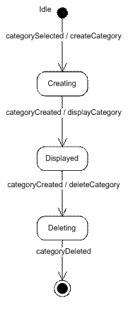
Figure 17: Category State Transition Diagram
When the customer selects a category it is created and displayed. If another category is created this one is deleted and no longer displayed.
A.5.1.3 Customer States and Transitions
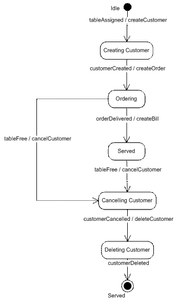
Figure 18: Customer State Transition Diagram
Once a customer has been assigned to a table, the customer is created. Once the customer exists an order is created for that customer. The customer orders items from the menu onto the order. When the order is delivered the bill is created and displayed to the customer. The customer is served, and may be eating or paying their bill. The customer may be deleted from the table anytime and the table becomes free.
A.5.1.4 Kitchen States and Transitions
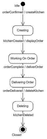
Figure 19: Kitchen State Transition Diagram
The kitchen is created when an order is confirmed. The order is displayed to the kitchen until the kitchen confirms that the order is delivered. Once the order has been delivered the order is deleted from the kitchen display.
A.5.1.5 Menu States and Transitions
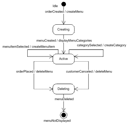
Figure 20: Menu State Transition Diagram
The menu is created once a customer has been assigned to a table and an order created. The menu class allows the customer to select menu items from menu categories. The menu allows the customer to display menu categories or items on the menu. The menu remains displayed until the customer places their order or is unassigned from the table.
A.5.1.6 Menu Item States and Transitions
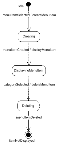
Figure 21: MenuItem state Transition Diagram
The menu item is displayed when it is selected for display from the menu. When a category is selected the menu item display is deleted.
A.5.1.7 Order States and Transitions
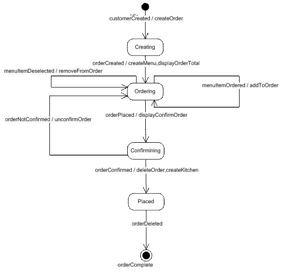
Figure 22: Order State Transition Diagram
An order is created once a customer has been assigned to a table. The order creates the menu. While the menu class is active, the customer may add or remove items on the order. When the customer places the order the customer is asked to confirm their order. If the customer decides to change their order, the menu is displayed and the customer continues ordering. If the customer confirms the order, the kitchen is created, and the order is deleted.
A.5.1.8 Receipt States and Transitions

Figure 23: Receipt State Transition Diagram
The receipt is created and displayed to the customer. Once the customer prints a copy of the receipt it is deleted.
A.5.1.9 Restaurant States and Transitions
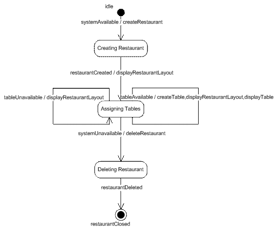
Figure 24: Restaurant State Transition Diagram
Whil the system is operational, the status of each table is continually updated on the restaurant display. Tables may be assigned or reserved as unavailable.
A.5.1.10Table States and Transitions
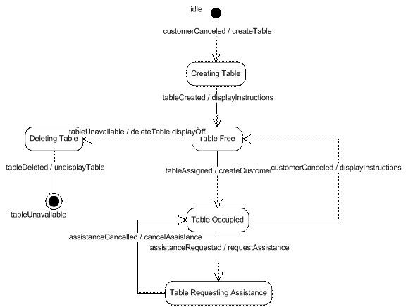
Figure 25: Table State Transition Diagram
Tables are made available by the restaurant. Once available a table may be assigned to a customer, in which case it becomes occupied. While occupied a customer may request assistance from the restaurant. The restaurant may cancel the assistance request at any time. Once the customer at the table has been canceled the table is made available.
A.5.2 Application Realizations
The following diagrams show events that are triggered by operations between class instances.
A.5.2.1 System Event Sequence Diagram
The system hierarchy indicates the sequence in which objects are activated.
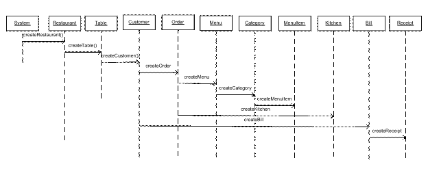
Figure 26: Class Hierarchy
When the system is active, the restaurant is created and may be used for business. While active the restaurant may make tables available or unavailable. When a customer is assigned to a table the customer is created. The customer assignment creates an order and this in turn creates a menu with which to fulfill the order. The menu creates categories for display to the customer. Categories may create menu items for display to the customer. The customer places menu items on (or removes from) the order until they place the order. When the order is confirmed, a kitchen object is created. When the kitchen delivers the order, a bill is created. Once the bill is paid a receipt is created.
A.5.2.2 Serve Customer Realization
How the Serve Customer use case is realized by the system objects.
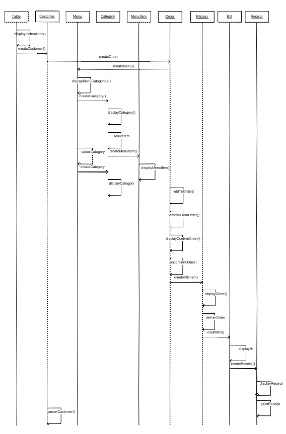
Figure 27: Serve Customer Use Case Realization
|
Use Case Event
|
Class Operations
|
|
customerSeated
|
displayInstructions
|
|
menuSelected
|
displayCategories
removeFromOrder
|
|
categorySelected
|
selectCategory
displayCategory
|
|
updateOrder
|
addToOrder
removeFromOrder
|
|
itemSelected
|
selectItem
displayMenuItem
|
|
orderSelected
|
displayOrder
|
|
orderCanceled
|
unconfirmOrder
|
|
orderConfirmed
|
displayConfirmOrder
displayOrder
|
|
orderDelivered
|
deliverOrder
displayBill
|
|
orderPaid
|
displayReceipt
printReceipt
|
|
orderComplete
|
cancelCustomer
|
Figure 28: Table 1: Use Case -> Class Operation Mapping
A.5.2.3 Maintain Restaurant Realization
How the Maintain Restaurant use case is realized by the analysis objects.
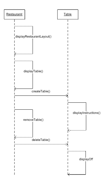
Figure 29: Maintain Restaurant Realization
|
Use Case Event
|
Class Operations
|
|
restaurantDisplayed
|
displayRestaurantLayout
|
|
tableAvailable
|
displayTable
displayInstructions
|
|
tableUnavailable
|
removeTable
displayOff
|
|
restaurantDisplayUnavailable
|
deleteAllTables
|
Table 2: Use Case -> Class Operation Mapping
A.5.2.4 Request Assistance System Realization
How the Request Assistance use case is realized by the system objects and their operations.
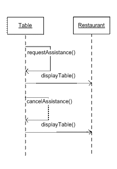
Figure 30: Request Assistance Use Case Realization
|
Use Case Event
|
Class Operations
|
|
assistanceRequested
|
requestAssistance
displayTable
|
|
assistanceCancelled
|
cancelAssistance
displayTable
|
Figure 31: Table 2: Use Case -> Class Operation Mapping
A.6 Class Diagram Operations
The following operations are containers for the requirements for the system.
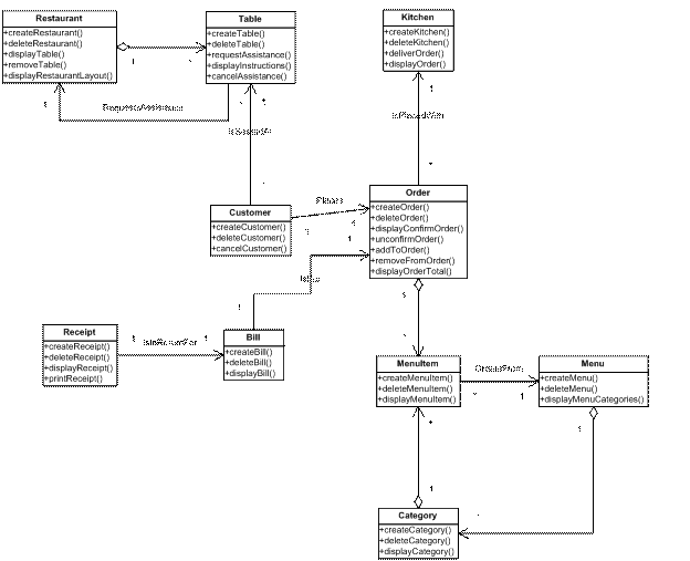
Figure 32: Class Operations Diagram
The following operations are derived from the events that pass between objects of the model [7].
Create and Delete operations are added purely for execution of the model.
These are ordered by class, as follows:
A.6.1 Bill
A.6.1.1 Display Bill
Upon the kitchen selecting delivery of a table order, the bill for that order will be displayed to the customer at that table.[9]
A.6.2 Category
A.6.2.1 Display Category
Upon a category being selected the available menu items and category description as stored in the database, will be displayed to the customer.
A.6.3 Customer
A.6.3.1 Cancel Customer
Upon selection of the cancel customer command by the head waiter, the table will be made available on the restaurant display.
A.6.4 Kitchen
A.6.4.1 Display Order
Upon confirmation of an order by a customer, the order will be displayed to the kitchen.
A.6.4.2 Deliver Order
Upon selection of delivery of an order by the kitchen, the order will be removed from the kitchen display.
A.6.5 Menu
A.6.5.1 Display Menu Categories
Upon a selecting the menu for a table the system will display categories that are set as available in the database, to the customer.
A.6.6 Menu Item
A.6.6.1 Display Menu Item
Upon a menu item being selected for display the menu item description, as stored in the database, will be displayed to the customer.
A.6.7 Order
A.6.7.1 Display Order Total
While a customer is ordering the total cost of the order will be displayed to the customer.
A.6.7.2 Display Confirm Order
Upon a customer selecting order, the current order and its menu items will be displayed to the customer for confirmation.
A.6.7.3 Unconfirm Order
Upon a customer unconfirming an order, the order will be removed from the display, and the menu displayed.
A.6.7.4 Add To Order
When a menu item is selected for addition to the order the order will be updated with the menu item added.
A.6.7.5 Remove From Order
When a menu item that is added to the order is selected for removal from the order the order will be updated with the menu item removed.
A.6.8 Receipt
A.6.8.1 Display Receipt
Upon confirmation of a bill being paid by the head waiter, the receipt for that bill will be displayed to the customer.
A.6.8.2 Print Receipt
Upon a request from a customer to print a displayed receipt, the system will print the receipt at the customer table.
A.6.9 Restaurant
A.6.9.1 Display Restaurant Layout
When the restaurant system is available, the tables in the restaurant will be displayed, with an indication of whether they are currently available or unavailable, occupied or unoccupied.
A.6.9.2 Display Table
Upon an unavailable table being selected as available, that table will be displayed as available.
A.6.9.3 Remove Table
Upon an available table being selected, the table will be displayed as unavailable.
A.6.10 Table
A.6.10.1Request Assistance
Upon receiving a requesting assistance message from the menu system display, the system will inform the restaurant display of the table requesting assistance.
A.6.10.2Cancel Assistance
Upon receiving a message from a menu display to clear the table assistance the system will remove the message from the restaurant display.
A.6.10.3Display Instructions
When a customer has been canceled from a table or the table has become available on the restaurant display, the table will display the instructions page.
A.6.10.4Display Off
When a table is made unavailable the customer display is turned off.
A.6.11 Supplementary Requirements
For each requirement listed above, identify additional information that is needed by that requirement and reference the requirement.
A.6.11.1Performance
A.6.1 to A.6.10 - All appropriate systems outputs will be displayed within 1 second of a command being entered.
A.6.11.2Display
A.6.1.1 – The bill will be itemized by menu item costs, taxes and total.
A.6.7.1 – The order will display each menu item ordered and its associated cost.
A.6.8.1 – the receipt will include the total cost, taxes, tip and method of payment.
A.6.11.3Internationalisation
A.6.6.1 – The display of menu item description will allow for characters from the English, French, Swedish and Italian alphabets.
A.7 Design Model
The design model packages the analysis classes into subsystems, creates methods from the class operations and assigns code specific types to the class attributes.
A.7.1 Use Case Storyboards
How the Serve Customer use case is realized by the user interface.
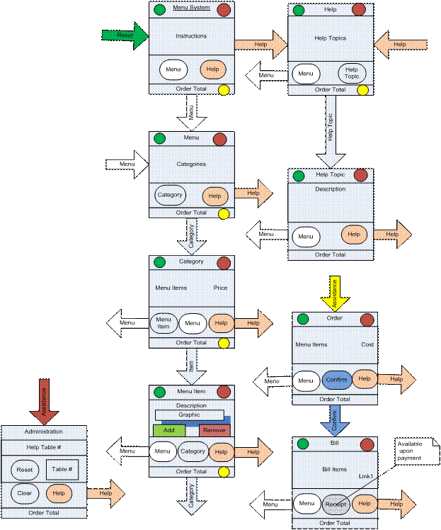
Figure 33: Menu System Use Case Storyboard
A.7.2 Design Subsystems
TBD.
A.7.3 Database Diagram
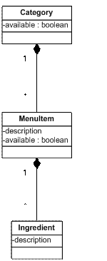
Figure 34: Potential Changes To The Database
NOTE: Full article at http://www.umllmu.com/pages/Blogs/Frames/AppendixA.htm
Author: Leslie Munday, Sr. IT Professional
Leslie is a Senior level Information Technology (IT) professional with expertise in Business and Systems Analysis, Process Analysis, Requirements Analysis and Project Management.
Footnotes:
A vision may also be applied to an application – in this case its intention is to describe an objective for improving the application.
‘Benefit’ is not a well-defined term. It should be a role outside of the use case worker roles.
Ivar Jacobson name for an included, but non-complete use case. This is called out purely for readability reasons.
Note that the actors have become the roles that ingratiate the use case.
Existing, meaning that components are not part of this development effort, although budget needs to be allocated for work performed on these components in order to deploy the application.
The format of the use case text is the default used by Rational RequisitePro
When designing the model, it might be prudent to combine these bill and receipt classes.
If the model is complete, consistent and can be verified by executing the model, then it implies that every functional requirement has been captured by an operation. [I have no proof for this statement.]
‘Customer’ means the ‘customer display’ for the sake of the requirements.
The storyboard is purely an example, and does not reflect the needs of the actual requirements for the menu system.
Not in scope for this project, but will require a change request for the database.
|